TIAs are the most powerful type of time measurement instruments. In addition to the functions provided by traditional “frequency counters”, “time interval counters” and “universal counters”, TIAs include new functions, run at a much higher rate, provide a continuous measurement capability, and report results together with their time of occurrence. These capabilities give you much more insight into the dynamic nature of your signal and much higher throughput.
This difference in capability is similar to the difference between voltmeters and oscilloscopes. Although both voltmeters and scopes measure the voltage of a signal, the scope provides much faster sampling and displays the results vs. time. For example, the voltmeter may be able to make 1000 measurements per second, which you can log with a computer. You may also log the time of occurrence of each measurement and display a plot of voltage vs. time. This plot looks a lot like an oscilloscope display but it only works for signals with very slow voltage variations. The scope on the other hand can sample the voltage at gigahertz rates and displays a plot of these samples vs. time. It therefore provides much more insight into the variations in the signal.
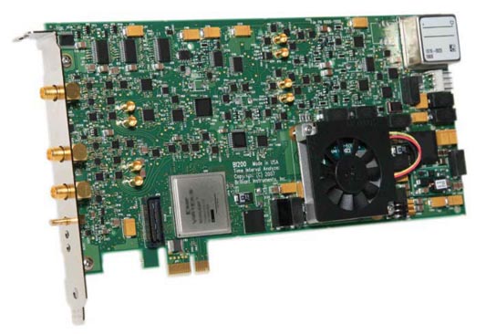
The BI200 TIA (Figure 1) can make 4 million measurements per second. Each of these measurements can be an instantaneous frequency measurement, a time interval measurement, or any of one of 10 measurement functions. For time measurements, each of the measurements would have a resolution of 3 ps. For frequency measurements, each measurement would provide 5 digits of resolution. As the measurement rate is decreased, the frequency resolution is improved.
 |
|
| Figure 1. | BI200 time interval analyzer. |
How does it work?
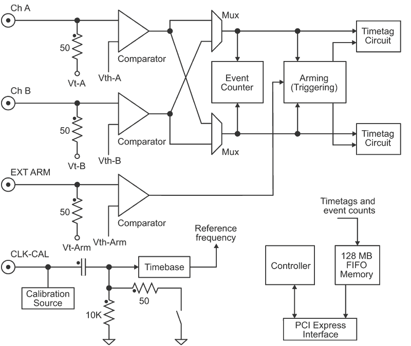
The simplified block diagram in Figure 2 shows the key components of the instruments from the user’s point of view. The input signal is terminated by 50 ohms to a user-programmable voltage (Vt) and fed to a comparator. The comparator output goes high when the signal crosses a user-programmable threshold voltage (Vth). At this point the signal is a digital waveform whose rising or falling edges are considered to be “events”. These events are continuously counted by the Event Counter, while the Arming System selects the edges which are to be timetagged according to the user configuration. For example, you can set up the instruments to timetag every N events, or every T seconds.
 |
|
| Figure 2. | BI200 simplified block diagram. |
When an event is timetagged, the event count (pulse number) and the time of the occurrence are logged to memory. The Timetag Circuits require a recovery time of 250 ns to be ready for another timetag. Note, however, that the signal is still counted by the Event Counter, so no information is lost. This recovery time means that up to 4 million timetags (or pairs of timetags) can be logged per second. From this timetag data, the instruments calculate the measurement results Figure 3.
 |
|
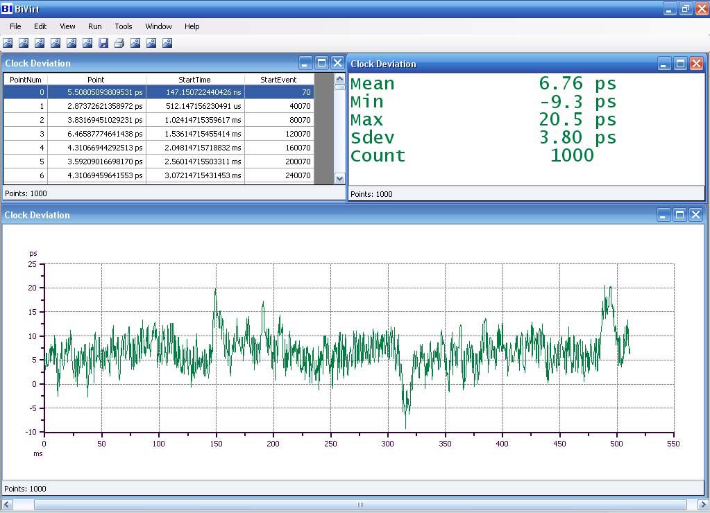
| Figure 3. | Screen shot of the measurement of an actual clock signal with crosstalk disturbance. |
About Brilliant Instruments
Brilliant Instruments, Inc. is a leading manufacturer of precision time and frequency measurement instruments for research and automated test applications. BI's products are in use worldwide by major research laboratories (NIST, Jet Propulsion Lab, US Naval Observatory), by semiconductor manufacturers for production testing of millions of devices on a 24 hour basis, and others.
BI's mission is to reduce the cost of test significantly by implementing business models that take advantage of new information technologies, and by using innovative instrument architectures.
Shalom Kattan is the founder and President of the company. He is a 28-year veteran of the precision time industry, including Hewlett Packard's frequency counter division and Guide Technology, Inc. (also known as GuideTech), where he developed a line of counters and time interval analyzers.
Shalom Kattan
Max Freq. (All Func.) - This is the maximum frequency for all measurement functions without prescaling (frequency division)
Max Freq. (Freq. Func.) - This is the maximum frequency for the frequency-type functions (1C1E) when using the prescaler for products with a prescaler (frequency division). See the datasheet for details.
Time Resolution - The single-shot time resolution of the hardware.
Freq. Resolution - The resolution for Frequency Average and Period Average functions is dependent on the single-shot time resolution and the duration of the measurement (effective gate time). It is easier to specify it as a number of digits per second. For example, 12 digits/s means that you will get 12 digits of frequency resolution with a 1 second gate time, or 9 digits in 1 millisecond. If the signal input is 1 MHz, 9 digits of resolution translates to 0.001 Hz resolution.
Meas. Rate - The maximum number of measurements per second that the instrument can take. This is due to the recovery time of the measurement circuits. Time interval analyzers (as opposed to traditional counters) still count the pulses (events) of the input signals during this recovery time, but no timetags are produced. For example, if the input frequency is 100 MHz and the instrument has a measurement rate of 4 MSa/s then a measurement can be made as often as every 25 cycles of the input.
Min. Pulse Width - The minimum pulse width for the input signal.
| Models | ||||||||||||||||||||||||||||||||||||||||
|
