Mitchell Lee, Linear Technology
LT Journal of Analog Innovation
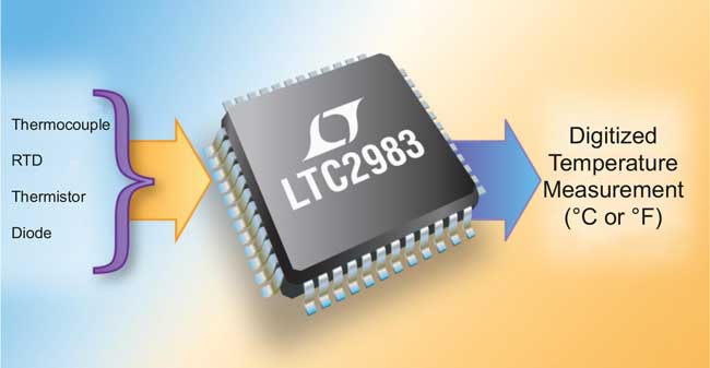 |
| The LTC2983 solves the unique problems presented by all standard temperature sensors to produce unmatched conformity and ease-of-use. |
Temperature measurement is not new. Galileo invented a rudimentary thermometer capable of detecting temperature changes, and two hundred years later, Seebeck discovered the thermocouple. Given the long history of temperature measurement and its extensive use today, one would think that accuracy problems were all but eliminated. Not so. Even though methods for extracting temperature from sensor elements are well known, accurately measuring temperatures to better than 0.5 °C or 0.1 °C accuracy remains a challenge. The LTC®2983 enables up to 0.1 °C temperature conformity (measured accuracy against a precision temperature calibrator), as shown in Figure 1.
 |
|
| Figure 1. | Typical temperature error conformity of the LTC2983 with various sensors. |
Thermocouples, temperature dependent resistance elements (RTDs and thermistors) and semiconductor elements (diodes) are widely used to electrically measure temperature. Digitizing the electrical signals of these sensor elements requires significant expertise in a number of areas: sensor behavior, analog circuit design, digital circuit design and firmware development. The LTC2983 packs this expertise into a single IC and solves each of the unique challenges associated with thermocouples, RTDs, thermistors and diodes. It combines all analog circuitry necessary for each sensor type with temperature measurement algorithms and linearization data to directly measure each sensor and output the result in °C.
Thermocouples: Overview
Thermocouples generate voltage as a function of the temperature difference between the tip (thermocouple temperature) and the electrical connection on the circuit board (cold junction temperature). In order to determine the thermocouple temperature, an accurate measurement of the cold junction temperature is required; this is known as cold junction compensation.
The cold junction temperature is usually determined by placing a separate (non-thermocouple) temperature sensor at the cold junction. The LTC2983 allows diodes, RTDs, and thermistors to be used as cold junction sensors. In order to convert the voltage output from the thermocouple into a temperature result, a high order polynomial equation (up to 14th order) must be solved (using tables or mathematical functions) for both the measured voltage and the cold junction temperature. The LTC2983 has these polynomials built in for all eight standard thermocouples (J, K, N, E, R, S, T and B) as well as user-programmed table data for custom thermocouples. The LTC2983 simultaneously measures the thermocouple output and the cold junction temperature, and performs all required calculations to report the thermocouple temperature in °C.
Thermocouples: What’s Important
A thermocouple’s generated output voltage is small (< 100 mV full-scale) (see Figure 2). As a result, the offset and noise of the ADC making the voltage measurement must be low. Furthermore, it is an absolute voltage reading requiring an accurate/low drift reference voltage. The LTC2983 contains a low noise, continuously offset calibrated 24-bit delta-sigma ADC (offset and noise <1 μV) with a 10 ppm/°C max reference (see Figure 3).
 |
|
| Figure 2. | Thermocouple design challenges. |
A thermocouple’s output voltage can also go below ground when the tip is exposed to temperatures below the cold junction temperature. This complicates systems by either forcing the addition of a second negative supply or an input level shifting circuit. The LTC2983 incorporates a proprietary front end capable of digitizing signals below ground on a single ground-referenced supply.
 |
|
| Figure 3. | Thermocouple measurement using diode cold junction compensation. |
In addition to high accuracy measurements, thermocouple circuits need to incorporate noise rejection, input protection, and anti-alias filtering. The LTC2983 input impedance is high, with a maximum input current of less than 1 nA. It can accommodate external protection resistors and filtering capacitors without introducing extra errors. It includes an on chip digital filter with 75 dB rejection of both 50 Hz and 60 Hz or 120 dB of 50 Hz or 60 Hz.
Fault detection is an important feature of many thermocouple measurement systems. The most common fault reported is an open circuit (broken or unplugged thermocouple). Historically, current sources or pull-up resistors were applied to the thermocouple input in order to detect this type of fault. The problem with this approach is that these induced signals lead to errors and noise, and interact with input protection circuitry.
The LTC2983 includes a unique open circuit detection circuit that checks for a broken thermocouple just prior to the measurement cycle. In this case, the open circuit excitation current does not interfere with measurement accuracy. The LTC2983 also reports faults related to the cold junction sensor. It can detect, report and recover from electrostatic discharge (ESD) events that may occur when long sensor connections are used in industrial environments. The LTC2983 indicates via fault reporting if the measured temperature is above/below the expected range for the specific thermocouple.
Diodes: Overview
Diodes are inexpensive semiconductor-based devices that can be used as temperature sensors. These devices are typically used as the cold junction sensor for a thermocouple. When an excitation current is applied to a diode, they generate a voltage as a function of temperature and the current that is applied. If two perfectly matched excitation current sources of known ratio are applied to the diode, a voltage of known proportionality to absolute temperature (PTAT) is output.
Diodes: What’s Important
In order to generate a PTAT voltage with known proportionality, two highly matched, ratioed current sources are required (see Figure 4). The LTC2983 accurately generates this ratio by relying on delta-sigma oversampling architecture. Diodes and the leads connecting to the ADC contain unknown parasitic diode effects. The LTC2983 contains a 3-current measurement mode that removes parasitic lead resistances. Various diode manufacturers specify different diode non-ideality factors. The LTC2983 allows individual programming of each diode’s non-ideality factor. Since absolute voltages are measured, the value and drift of the ADC reference voltage are critical. The LTC2983 includes a factory trimmed 10 ppm/°C max reference.
 |
|
| Figure 4. | Diode design challenges. |
The LTC2983 automatically generates the ratioed currents, measures the resultant diode voltages, calculates the temperature using the programmed non-ideality and outputs the results in °C. It can also be used as the cold junction sensor for thermocouples. If the diode is broken, shorted or inserted incorrectly, the LTC2983 detects this fault and reports it in the conversion result output word and the corresponding thermocouple result, if it was used to measure the cold junction temperature.
RTDs: Overview
RTDs are resistors that change value as a function of temperature, and can measure temperatures over a wide temperature range, from as low as –200 °C to 850 °C. In order to measure one of these devices, a low drift, precision sense resistor is tied in series with the RTD. An excitation current is applied to the network and a ratiometric measurement is made. The value, in ohms, of the RTD can be determined from this ratio. This resistance is used to determine the temperature of the sensor element using a table lookup.
The LTC2983 automatically generates the excitation current, simultaneously measures the sense resistor and RTD voltage, calculates the sensor resistance and reports the result in °C. The LTC2983 can digitize most RTD types (PT-10, PT-50, PT-100, PT-200, PT-500, PT-1000 and NI-120) and has built in coefficients for many standards (American, European, Japanese and ITS-90).
RTDs: What’s Important
A typical PT100 RTD (see Figure 5) resistance varies less than 0.04 Ω per tenth of 1°C corresponding to a signal level of 4 μV at 100 μA current excitation. Low ADC offset and noise are critical for accurate measurements. The measurement is ratiometric relative to the sense resistor; the absolute values of the excitation current and reference voltage are not as important when calculating the temperature.
 |
|
| Figure 5. | RTD design challenges. |
Historically, the ratiometric measurement between the RTD and sense resistor was performed with a single ADC. The sense resistor’s voltage drop was used as the reference input of the ADC measuring the RTD voltage drop. This architecture requires 10 k or larger sense resistors, which must be buffered to prevent droop due to the ADC reference input dynamic currents. Since the sense resistor value is critical, these buffers need to have low offset, drift and noise. This architecture makes it difficult to rotate current sources in order to remove parasitic thermocouple effects. Delta-sigma ADC reference inputs are much more susceptible to noise than the inputs, and small values of reference voltage can lead to instability.
These problems are solved by the LTC2983’s multiple ADC architecture (see Figure 6). The LTC2983 uses two highly matched, buffered, auto-calibrated ADCs, one for the input and one for the reference. They simultaneously measure both RTD and RSENSE, calculate the RTD resistance and apply this to a ROM-based lookup table to ultimately output the RTD temperature in °C.
 |
|
| Figure 6. | RTD temperature measurement using the LTC2983. |
RTDs come in several configurations: 2-wire, 3-wire and 4-wire. The LTC2983 accommodates all three configurations with a configurable single hardware implementation. It can share a single sense resistor among multiple RTDs. Its high impedance input allows external protection circuits between the RTD and ADC inputs without introducing errors. It can also autorotate the current excitation to eliminate external thermal errors (parasitic thermocouples). In cases where parasitic lead resistance of the sense resistor degrades performance, the LTC2983 allows Kelvin sensing of RSENSE.
The LTC2983 includes fault detection circuitry to determine if the sense resistor or RTD is broken or shorted. It warns if the measured temperature is above or below the maximum specified for the RTD. When an RTD is used as the cold junction sensor for a thermocouple, three ADCs simultaneously measure the thermocouple, the sense resistor and the RTD. RTD faults are passed to the thermocouple result and the RTD temperature is automatically used to compensate for the cold junction temperature.
Thermistors: Overview
Thermistors are resistors that change value as a function of temperature. Unlike an RTD, a thermistor’s resistance varies many orders of magnitude over their temperature range. In order to measure one of these devices, a sense resistor is tied in series with the sensor. An excitation current is applied to the network and a ratiometric measurement is made. The value, in ohms, of the thermistor can be determined from this ratio. This resistance is used to determine the temperature of the sensor solving Steinhart-Hart equations or table data.
The LTC2983 automatically generates the excitation current, simultaneously measures the sense resistor and thermistor voltage, calculates the thermistor’s resistance and reports the result in °C. Thermistors typically operate from –40 °C to 150 °C. The LTC2983 includes coefficients for calculating the temperature of standard 2.252k, 3k, 5k, 10k and 30k thermistors. Since there is a large variety of thermistor types and values, the LTC2983 can be programmed with custom thermistor table data (R vs T) or Steinhart-Hart coefficients.
Thermistors: What’s Important
A thermistor’s resistance (see Figure 7) varies many orders of magnitude over its temperature range. For example, a thermistor measuring 10 k at room temperature can go as low as 100 Ω at its highest temperature and > 300 k at its lowest, while other thermistor standards can go above 1 M.
 |
|
| Figure 7. | Thermistor design challenges. |
Typically, in order to accommodate large valued resistance, very small excitation current sources are used in conjunction with large sense resistors. This results in very small signal levels at the low end of the thermistor’s range. Input and reference buffers are required to isolate the ADC’s dynamic input current from these large resistors. But buffers don’t work well near ground without separate supplies and offset/noise errors need to be minimized.
These problems are all solved by the LTC2983 (see Figure 8). It combines a proprietary, continuously calibrated buffer capable of digitizing signals at or even below ground with its multiple ADC architecture. Two matched, buffered ADCs simultaneously measure the thermistor and sense resistor and calculate (based on the standard) the thermistor temperature in °C. Large value sense resistors are not required, allowing multiple RTDs and thermistors of different types to share a single sense resistor. The LTC2983 can also auto-range the excitation current depending on the thermistor’s output resistance.
 |
|
| Figure 8. | Thermistor temperature measurement using the LTC2983. |
The LTC2983 includes fault detection circuitry that can determine if the sense resistor or thermistor is broken/shorted. It warns if the measured temperature is above or below the maximum specified for the thermistor.
The thermistor can be used as the cold junction sensor for a thermocouple. In this case, three ADCs simultaneously measure the thermocouple, the sense resistor and the thermistor. Thermistor faults are passed to the thermocouple result and the thermistor temperature is automatically used to compensate the cold junction temperature.
Universal Measurement System
The LTC2983 can be configured as a universal temperature measurement device (see Figure 9). Up to four sets of universal inputs can be applied to a single LTC2983. Each of these sets can directly digitize a 3-wire RTD, 4-Wire RTD, thermistor or thermocouple without changing any onboard hardware. Each sensor can share the same four ADC inputs and protection/filtering circuitry, configured using software. One sense resistor is shared among all four banks of sensors and cold junction compensation is measured by a diode. The LTC2983 input structure allows any sensor on any channel. Any combination of RTDs, sense resistors, thermistors, thermocouples, diodes and cold junction compensation can be applied to any and all the 21 analog inputs on the LTC2983.
 |
|
| Figure 9. | Universal temperature measurement system. |
Conclusion
The LTC2983 is a groundbreaking, high performance integrated temperature measurement system that directly digitizes thermocouples, RTDs, thermistors and diodes with laboratory grade precision. It features high accuracy, an easy sensor interface and tremendous flexibility.
Its three 24-bit delta-sigma ADCs use a proprietary front end to solve many problems typically associated with temperature measurements. High input impedance with live-at-zero input range enables direct digitization of all temperature sensors and easy input projection. Twenty flexible analog inputs allow a single hardware design to measure any sensor by simply reprogramming the device through the SPI interface.
The LTC2983 automatically performs cold junction compensation, can use any sensor to measure the cold junction and includes fault reporting. It can directly measure 2-, 3- or 4-wire RTDs, and can easily share sense resistors to save cost and rotate current sources to remove parasitic thermal effects. It includes auto-ranging current sources for increased accuracy and reduced noise associated with thermistor measurements.
In addition to the built-in sensor profiles, the LTC2983 enables custom, user-programmable sensor profiles to account for nonstandard, table-driven RTDs, thermocouples and thermistors.
