Arthur Russell, Vicor Corporation
EDN
There are a variety of reasons why a system designer may want to consider paralleling of DC power supplies. Some of these are related to the bill of materials and logistics issues, others are focused on satisfying system current, performance or reliability objectives.
On the non-design side, the ability to parallel supplies may allow a single supply model to be used singly or in combinations across a broad product line. This can simplify sourcing, increase per-unit volume, and streamline inventory management.
The technical reasons to consider paralleling supplies are more complex, of course. First, using parallel supplies can be a form of "insurance" in case the product actually needs more current than budgeted, perhaps due to unavailability of lower-power components or new features and capabilities added by marketing. Second, parallel supplies may support N+1 and even N+2 redundancy to safeguard against single-point failures, or to enable hot-swapping of a failed supply without system impact. Third, it permits the use of a known, proven supply with well-understood features, characteristics and form factor, thus reducing design-in risk and uncertainty. Finally, it allows for "heat spreading" by adding flexibility in physical placement of the power converters, if a single higher-capacity unit would dissipate too much heat in a highly localized area.
The flexibility and potential benefits offered by the paralleling of supplies brings an obvious question: can any supply be used, as-is, in parallel configuration? The answer is "no." It depends on the design of the supply, the technique used to connect the supplies, and the reason the supplies are being used in parallel.
The most obvious and simplest way to hope to put supplies in parallel is to simply tie their outputs together. In general, this won't work, as each supply has its own output voltage regulation, and so would be trying not only to maintain this regulation versus changes in load, but also attempting to regulate against the closed-loops of the other supplies.
For supplies which include their own traditional internal error amplifier and reference, just placing multiple supplies in parallel is not an effective way to make a high power array. Parametric differences from supply to supply will always cause one supply – the one with the highest output-referred reference voltage – to carry all of the load current, while all of the remaining supplies will carry no load.
In this case, as the load exceeds the capability of this "lead" supply, it may enter a constant-current limit mode (which may or may not be a rated mode of operation), or it may interpret the overload as a fault and shut down. Depending on the supply in question, these responses could lead to overstress, especially if they occur as part of regular operation in the application. Further, for cases where the supply shuts down due to an overload, the supply in the array with the next-highest reference voltage will be forced to carry the entire load, and will similarly shut down. This will quickly lead to collapse of the entire supply rail.
One way this direct-connect topology can work well is if one supply is set to constant-voltage (CV) mode and the others are set to constant-current (CC) mode, but at slightly higher output voltage; note that not all supplies allow choice of output mode. The supplies which are set to the higher output voltage will provide constant-current output, and each of their output voltages will drop until it equals the output of the CV supply. The load must draw enough current to ensure that the supplies which are in CC mode must stay in that mode. Note that use of the two modes does mean that the multiple supplies are no longer strictly identical, thereby negating some of the advantages of the parallel configuration.
The direct-connect approach is viable if the supply is specifically designed to support that topology, or if there is a single control-loop error amplifier which feeds the error signal back to all of the other supplies, so they share the load. However, the latter method also requires a "share bus" for the control signals from the master to the slaves.
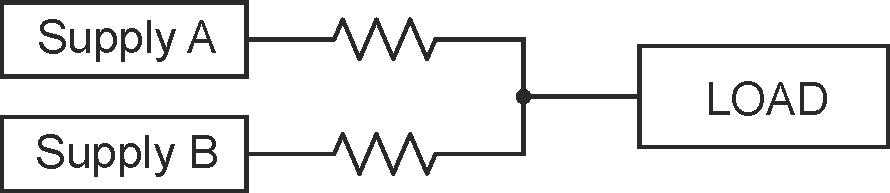
Another approach adds small ballast resistors in series with each supply’s output, to equalize the distribution of the load current among the supplies in the array even when their control loops are seeking dissimilar output voltages, as shown in Figure 1. The ballast resistors create some loss of load regulation, depending on the spread of setpoint errors that the ballasting intends to overcome. However, these ballast resistors also dissipate heat, which degrades system efficiency.
 |
||
| Figure 1. | One sharing approach is to use relatively low-value ballast resistors on each supply’s output, but this has issues due to resistor-related dissipation and overall efficiency. |
|
This "OR" that?
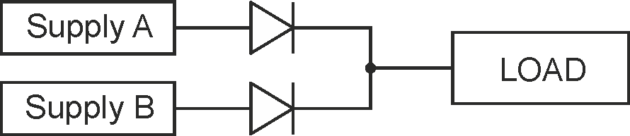
A seemingly "simple" solution to this direct-connect dilemma is to just use a diode between each supply and the common tie point of all supplies, a technique commonly referred to as diode-ORing, Figure 2. ORing diodes are very effective at preventing a supply from sinking current away from the shared output, but are generally insufficient to address sharing errors among supplies with independent error amplifiers, because the conduction knee is abrupt enough that parametric differences in the supplies’ setpoints will still lead to significant sharing imbalances.
 |
||
| Figure 2. | In principle, multiple DC-supply outputs can be combined by using diodes to isolate one supply from the other, but this configuration has many performance issues related to balance and current sharing. {from Vicor Back to Basics: What is Active ORing?} |
|
Diode ORing is generally required for supplies acting independently, whose outputs can both sink and source current (two quadrant-operation). The effect of directly paralleling such supplies without ORing diodes is far worse than it is for single-quadrant supplies. While single-quadrant supplies will only suffer from load-sharing errors, two-quadrant supplies will actively contend for control of the common output voltage. This will cause current in excess of the load current to circulate among the supplies in the array, and likely lead to immediate overload of one or more of the supplies.
Also, if the diodes have a negative temperature coefficient for their conduction threshold, they will actually promote current hogging in the array. One way to minimize the problem is to use a method of rectification with a positive tempco – Schottky diodes, or via a diode-like function but built using FETs and a rectifier in an active-ORing implementation – but diodes can reduce efficiency due to forward voltage drop, and active-ORing can add cost and complexity.
Under some circumstances, diode ORing can still offer reliability improvements at the system level. The chief case of interest is where one of the supplies suffers a shorted output FET or capacitor which could jeopardize the common output voltage rail. ORing diodes will quickly decouple that short from the output bus, and improve reliability and system robustness.
Who's in charge here?
Supplies generally must be designed specifically for parallel operation in order to operate reliably and predictably in an array. Startup synchronization, fault-protection coordination, and control-loop stability must all be considered.
For a parallel array of supplies to deliver increased levels of usable current to a load, some type of control-loop strategy that factors in array use is needed. A popular control strategy is to run the supplies with no internal voltage regulation amplifier, but instead group them together with a common control-signal input which is controlled by a single error amplifier. This error amplifier regulates the output of the system, and then its single feedback signal is distributed to all of the power supplies in the system.
A major benefit of this popular control strategy is the regulation of the output voltage is excellent, and sharing errors are dominated by part-to-part variations in modulator gain. On the downside, use of a single error amplifier and single wired control bus represents a single point of failure, which may present a problem for some types of high-reliability systems. Also, parametric errors on modulator gain can be difficult to control, often leading the manufacturer to trade off yield to control sharing errors.
For a single control-loop approach, sharing errors are minimized if the supplies feature tight tolerance on their control-node inputs. If the sharing errors are large, then either the power rating of the array must be reduced to avoid overloading of any single supply in the array due to sharing imbalances, or specific countermeasures need to be used. Techniques for sharing errors which result from part-to-part variations of the control node can include a production-based adjustment to calibrate out errors (an expensive approach), or adding a current-control loop around local to each supply inside the array to cancel such errors (which adds some complexity and parts). Sensing current for these local loops typically involves adding a shunt resistor to the supply.
There's a second obstacle for isolated power supplies that have their control nodes referred to the primary side of the DC-DC: transmitting the output of the error-amplifier across the primary-to-secondary isolation boundary. Isolation techniques often add cost, take valuable board real-estate, and can have adverse effects on reliability, depending on the isolation components used.
A second control-loop strategy which permits separate supplies to be arranged in a parallel array uses a load line to emulate the path resistance of the ballast resistor method. By implementing what is called the "droop-share" method of load sharing, each supply has a separate reference and integrating error amplifier, but the reference is deliberately and linearly reduced by some nominal amount as the load current of the supply increases.
Paralleling supplies may have negative consequences on transient response and load regulation. The droop-share method deliberately uses a negative load-regulation term to distribute the load across modules in the array. Therefore, load regulation tends to be worse for droop-share arrays than for arrays created with a single traditional error amplifier. If this is a problem, an external control loop can be used around the droop-share array, to effectively cancel out the negative-regulation term. The resulting static-regulation error is identical to the traditional error-amplifier case, since the external loop is itself an error integrator.
Supply design can simplify, enhance parallel configurations
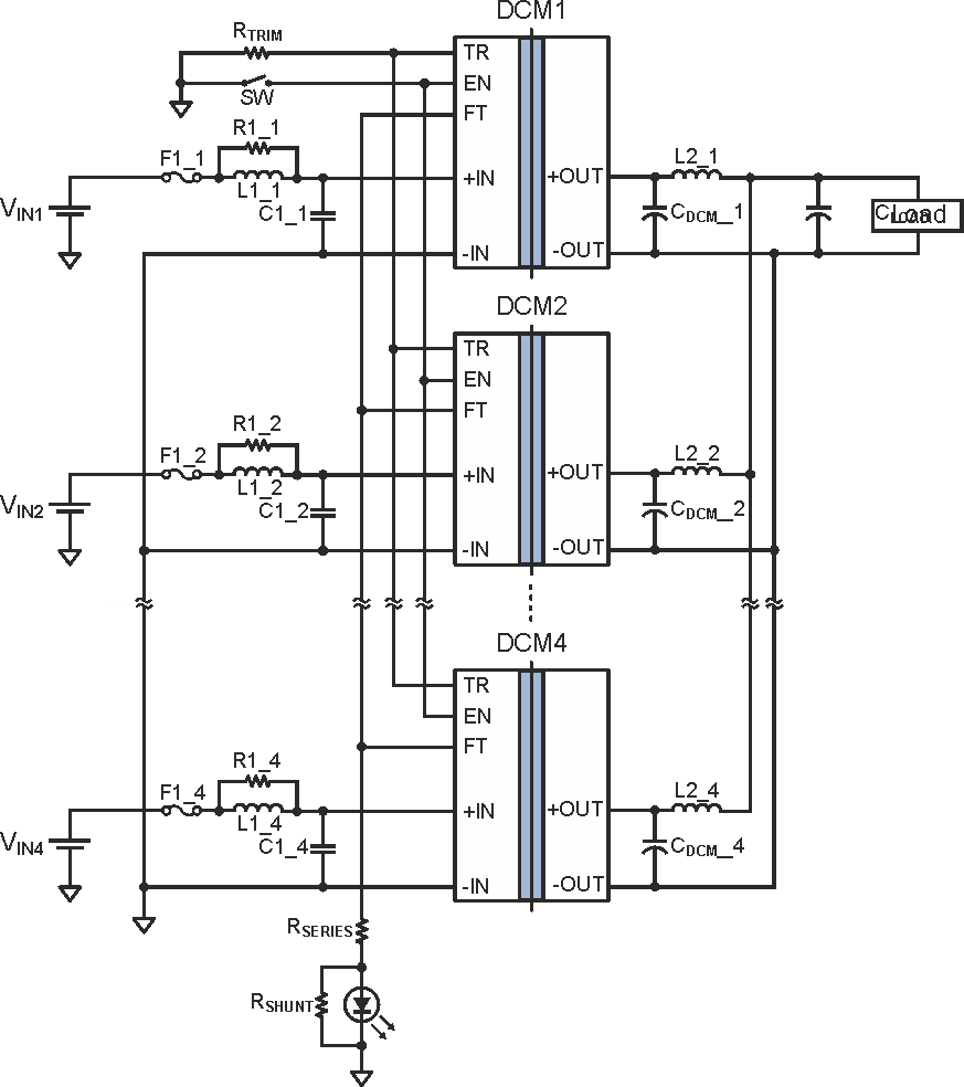
Supply vendors can take steps to ease the paralleling challenge. For example, Vicor’s DCM DC-DC converters in Converter housed in Package (ChiP) packaging feature a built-in negative-slope load-line; thus, as the load increases, the DCM's internal regulator reduces the output voltage slightly. This effectively acts like the small ballast resistor approach but without any actual resistors, Figure 3, and with a few additional key differences.
 |
||
| Figure 3. | Vicor's DCMs in ChiP packaging are designed to be paralleled by simply connecting their outputs together; no diodes, ballast resistors, or other load-balancing components are needed. {from Vicor Application Note AN-030: Parallel DCMs, Figure 1} |
|
First, it’s a different way to implement a ballast resistor, and one which doesn’t involve wasted heat as there is no physical resistor and no V×I heat generated. A second difference relates to dynamic response, since for frequencies up to hundreds of kilohertz, a real resistor can be considered as having unlimited “bandwidth” in its I-V transfer-function curve due to lack of high-frequency parasitic concerns. As a result, any instantaneous change in voltage across the resistor results in an immediate corresponding change in current.
In the DCM converters, the load line is implemented through a discrete-time modulation of the digital/analog converter that creates the reference for the error amplifier. The correct reference value is calculated primarily based on an estimate of the DCM's output current, and involves some averaging to reduce noise. Therefore, the resistor that the DCM load-line emulates is one that acts like it has a significant capacitor in parallel with it, and the resulting RC-time constant is evident when looking at the datasheet figures which show the supply's response to a load step.
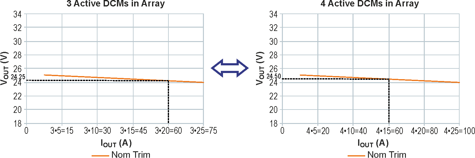
Nonetheless, having this load-line output characteristic permits multiple DCM outputs to be placed directly in parallel, while each still has its own error-amplifier control-loop still active. The distribution of the load current over the DCMs in the array is ideally equal if all DCMs have the same external (real) path resistances to the load, have the same trim setpoint, and are at the same temperature. Parallel DCMs thus behave like a single DCM but with a higher output current, Figure 4.
 |
||
| Figure 4. | With the Vicor DCM converters, units connected in parallel perform as a single converter; also, as the load-line shows, if the array is sized as N+1 redundant relative to the maximum load, the array continues to function despite the failure of any single converter. {from Vicor Application Note AN-030: Parallel DCMs, Figure 3} |
|
With the DCM converter family, temperature changes in individual units are not a problem due to their negative voltage-temperature coefficient. If one supply is loaded more than the others, its temperature will rise relative to the others, which in turn will cause its output voltage to decrease. Since the output voltages of the other parallel DCMs match that of the loaded DCM, their outputs would follow their load lines, increasing their share of the load current and bringing the circuit back to equilibrium.
The issues and approaches to paralleling DC-DC supplies apply to larger converters such as the DCM series from Vicor, but also to power-supply ICs which are intended for much-smaller loads. For example, the LT3083, a 3 A low-dropout (LDO) linear regulator from Linear Technology Corp., supports parallel operation using a 10-mΩ ballast resistor between each supply and their common output rail.
Using power supplies in parallel is an attractive and viable technique to realize benefits in inventory and stocking, product commonality, additional output current, and N+1 redundancy. However, it must be done with an understanding of the possible paralleling topologies, and well as how the closed-loop supply regulation will be maintained across the multiple supplies.
References
"Application Note AN-030: Parallel DCMs," Ugo Ghisla, Vicor Corp.
"Back to Basics: What is Active ORing?," Vicor Corp.
"Learn to connect power supplies in parallel for higher current output," Keysight Technologies.
"Power Tip 27: Parallel power supplies with droop method," Robert Kollman, Texas Instruments.
Figure 1: One sharing approach is to use relatively low-value ballast resistors on each supply’s output, but this has issues due to resistor-related dissipation and overall efficiency.
Figure 2: In principle, multiple DC-supply outputs can be combined by using diodes to isolate one supply from the other, but this configuration has many performance issues related to balance and current sharing.{from Vicor Back to Basics: What is Active ORing?}
Figure 3: Vicor's DCMs in ChiP packaging are designed to be paralleled by simply connecting their outputs together; no diodes, ballast resistors, or other load-balancing components are needed. {from Vicor Application Note AN-030: Parallel DCMs, Figure 1}
Figure 4: With the Vicor DCM converters, units connected in parallel perform as a single converter; also, as the load-line shows, if the array is sized as N+1 redundant relative to the maximum load, the array continues to function despite the failure of any single converter. {from Vicor Application Note AN-030: Parallel DCMs, Figure 3}
