Hi friends,
aim of this project is to present a way to store a large quantity of data into microSD card in files with FAT32 format. Here, ATmega32 is used for data collection and microSD interface. The data is received from in-build 8-channel ADC of ATmega32. One channel is used for reading temperature from LM35 sensor and remaining channels are used for simply reading voltages and storing them.
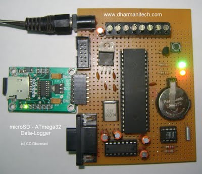
This project can be used to interface 8 different sensors with ADC of ATmega32, similar to the LM35 used here. The data is stored in CSV (comma separated values) format, which can be read using a PC/Laptop with Microsoft Excel or other compatible software. A snapshot of the excel file is given later in this post.
This project is an example of how to use the microSD FAT32 library presented in my earlier post. In that post, the files were created using hyper-terminal and entering data with the PC keyboard, since that demonstrates the file creation and it's easy to debug. But many users have requested to make the file creation independent of the terminal, done inside the microcontroller, so I'm showing here how to use those functions independent of terminal. If you have directly landed on this page, it would be more helpful if you visit the original post first as it would be a better starting place for learning SD or FAT32 functions.
Here is the schematic:
The project contains RTC interface on DS1307 (for date and time storage), RS232 on MAX232 (for connection with PC) and a microSD module. Here, the hyper-terminal connection is required only for setting RTC date and time. Once the date/time are set, the RS232 connection is not required anymore for normal data-logging operation (It can be used for debugging purpose if there is a problem).
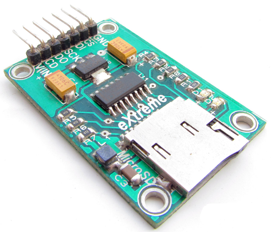
The microSD module used here is from eXtreme Electronics.
The module is shown in the figure here. Other than the microSD socket, this low-cost module also contains on-board 3.3v regulator for the microSD card, a 5v-3.3v level converter and other safety features required for the card. This module is used here as it provides a stable interface and makes the the card compatible with 5v supply and 5v signals of microcontroller.
The schematic also shows two LEDs and a push-button. The LEDs are used for indications of power and recording and the push-button is used to start-stop recording.
Download schematic:
Schematic (PDF) - download
Schematic (EAGLE) - download
In the second part, we consider the operation of the system, procedures for each mode, the basic parameters to configure the system.
