Alan Yates
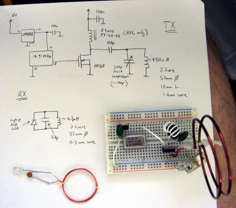
A lot of people have been asking me for the circuit of the demonstration TX I used in the video, so here it is:
This is *not* an efficient design and is meant as a demonstration only. The compression trimmer should be fairly high quality, but as the demo was on a solderless breadboard perhaps any old junk trimmer would work OK. The IRF510 is hardly the best device for this service. There should *really* be a gate-source resistor on the MOSFET, if the drive disappears it will probably smoke, the drive probably isn't within spec either.
The tuning is quite sharp. Peak the trimmer for best range using the LED receiver. You may need to tweak the 27 pF capacitor in the RX coil to match your particular coil inductance, use a trimmer if you prefer.
Other frequencies for the canned TTL oscillator module should work fine if you adjust the tuned circuits appropriately. I used my resonance calculator to get ballpark values then tweaked from there. It is also helpful if you can measure inductance with some precision, I used my Carver-style LC measurement device for that.
If you were designing for high efficiency I'd suggest a class-E amplifier approach, with link coupling to an otherwise completely floating tank circuit. The link winding size/angle could be adjusted WRT the tank to adjust the coupling to optimise matching for best efficiency into whatever load is reflected. It would be useful if you could predict/measure the impedance seen to optimise the power amplifier design, but an L or Pi network and standard antenna matching techniques can be used.
