PID stands for proportional-integral-derivative controller. This is a device used in control systems or simply to control other devices or other electronic systems. The main function of this controller is to help regulate or maintain the level of the different variables in the control system. The PID controller may function affecting only a single device or many other devices simultaneously. The typical application of the PID controller is found in the industrial and manufacturing areas.
 |
|
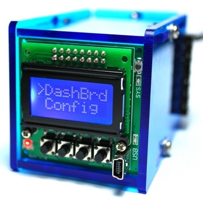
| Figure 1. | Open source PID-controller module. |
One of the various applications of the PID is the common temperature control of a particular household or area in a building. The thermostat is interfaced with a PID controller and the latter maintains or regulates the temperature of the area based from the desired temperature. This desired temperature is referred to as the setpoint or the ideal temperature. If the surrounding temperature rises or falls, the PID adjusts the level so that the thermostat maintains the desired level. Herein, the changing value of the temperature is the variable. PID controls this variable, which is changing with time, and tries to maintain the setpoint by varying the variable to meet the ideal temperature.
PID controllers and normal controllers are distinguished in the way each device function or based on their application. PID controllers employ advanced formula to contain and or preempt any flaw with the system. With PIDs, the smooth application or performance of the system is ensured to be as error-free as possible.
The osPID hardware has the same form factor as industrial PID controller. Unlike an industrial controller however, we wanted to provide flexible hardware that allows people to modify, change and hack to suit their applications. Arduino was chosen as a base platform for the osPID as many makers are familiar with it.
The osPID hardware has 3 core components:
- Main board: An Arduino-compatible main processing board with a user interface. Two edge connectors are used to connect to the input and output cards.
- Input card: An input card that can be swapped depending on desired type of input measurement.
- Output card: An output card that can be swapped depending on desired output type.
Both the input and output card come with a robust 6 pins 6.35 mm pitch barrier terminal block, instead of a smaller screw terminal block. Microcontroller peripherals like I2C, SPI, external analog reference, analog pins, digital IO pins and power are available to both cards.
The entire osPID design is open source hardware and the design files can be downloaded at the download section on the website. You are free to use & modify them to your own needs.
Main Board
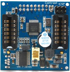
The core of the osPID hardware consists of a compact Arduino compatible board having a simple user interface. An ATMega328P running at 16 MHz is used as the main controller. An 8×2 alphanumeric character LCD with blue back light provides an intuitive user interface, with 4 push buttons for navigation.
 |
|
| Figure 2. | Main Board. |
Features
- Complete Arduino compatible board with ATMega328P-AU
- 8×2 LCD white character with blue back light & adjustable contrast
- On board USB-serial port
- 1 2×6 2.54 mm pitch edge card expansion slot for input card
- 1 2×6 2.54 mm pitch edge card expansion slot for output card
- 4 push buttons
- 1 red LED for power indication
- 1 yellow LED for system status and operation
- 1 green LED for USB activity status
- 1 buzzer with transistor for a loud and annoying sound
- 1 reset button
- Analog reference voltage with LC filter
- Auto reset selection through jumper
- 7 – 38 VDC input range
- 6-pin AVR In-circuit serial programming (ICSP) header
- Dimension – 46.99 mm × 46.99 mm
- Can be slotted into 1/16 DIN panel cutouts
- RoHS compliant – Yes
 |
|
| Figure 3. | osPID Main Board Schematic. |
An efficient buck converter is used for power conversion, this allows the osPID to accept up to 38 V input power without overheating. Being able to accept this higher voltage also leaves the door open for voltage output applications such as ±10 V or ±5 V.
An on-board USB to serial converter chip is available for connecting to our PC-based user interface software. This allows for more advanced configuration without overloading the on-board UI. We also added the in-circuit system programming (ICSP) connector in case you wanted to modify the bootloader residing on the ATMega328P or simply wanted to run it bare metal without Arduino.
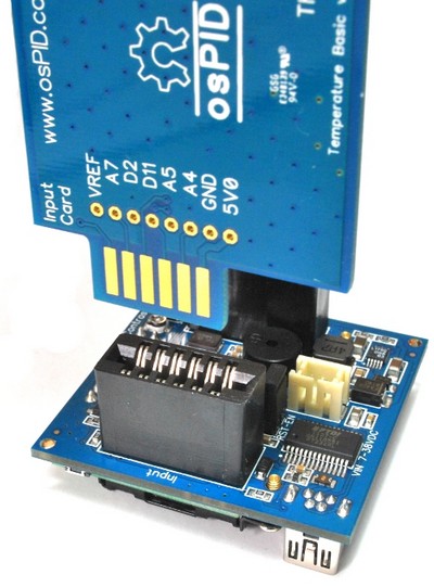
The main board is connected to the input & output cards through robust edge card connectors. We wanted the cost of the input & output cards to be as low as possible, as this is area most likely to be hacked by the end-user. By using these edge card connectors, no connectors are required on the input & output card side.
 |
|
| Figure 4. |
Main board is connected to the input & output cards through robust edge card connectors. |
Next Part - Input & Output cards, Firmware and Software
