Create the mathematical inverse of an analog voltage by converting it to frequency and measuring the period.
A popular series of inexpensive distance sensors integrates an infrared emitting diode, a linear charge-coupled-device array, and a signal-processing circuit in one unit. The output is a dc voltage, VS, that depends on the distance, D, in a nonlinear manner (Figure 1).
 |
|
| Figure 1. | The analog voltage directly from the sensor is not linear with the distance. |
To improve linearity, the manufacturer suggests using the relationship between the output voltage and the inverse value of the distance (Figure 2). You can use the curve-fitting utility of Excel software to calculate two or three coefficients of this alternative relationship, and a microcontroller can then use the coefficients to calculate distance from VS. The calculation requires floating-point arithmetic, which results in a large amount of machine-language code, a difficulty for many microcontrollers due to their limited memory size.
 |
|
| Figure 2. | Plotting the voltage against the inverse of the distance improves the linearity. |
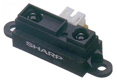 |
This Design Idea describes a way to present the sensor response with better linearity and a circuit that eliminates the need for complex calculations to find the distance. The built-and-tested unit uses the Sharp GP2D120 sensor (Reference 1), which measures distances of 4 to 30 cm (40 to 300 mm). This sensor is currently out of production but may be available through some sources. If not, a similar but untested replacement is the Sharp GP2Y0A21YK0F (Reference 2), which measures distances of 10 to 80 cm (100 to 800 mm).. |
 |
|
| Figure 3. | The new way of presenting the inverse of the sensor voltage against the distance provides the best linearity. |
 |
|
| Figure 4. | An AD654 VFC between the sensor and the microcontroller ensures a linear relation between pulse period and distance. A measurement calculates the 50Ω output impedance of the distance sensor. The LCD can be any generic device. |
Figure 3 shows the linearity improvement you gain by using the inverse value of the voltage, VS, versus distance. Figure 4 shows the circuit that provides a linear relationship between distance and another variable. The key component is a voltage-to-frequency converter, such as the AD654, between the sensor and the microcontroller (References 3 and 4). The sensor’s response is
where a and b are coefficients.
The VFC has a linear response:

where SF is a coefficient.
The pulse period is

The microcontroller defines the period as a number of internal clock pulses,

The period of clock pulses is 0.5 μsec, and it defines the values of the frequency-determining components of the VFC. From these equations, you can build a relationship between N and D:
which is a straight line. The hardware circuit’s design performs the calculations; they do not take place when the microcontroller calculates distance.
The RC network at the sensor output matches the sensor-voltage swing to the VFC’s input range and attenuates the 1-kHz noise riding on the sensor signal. The resistor divider modifies the system response to the form
where kD is the transfer ratio of the divider, α is the slope, and β is the offset.
Listing 1. Distance-Calculation Code
Measure LDAA  #$01          ; Clear IC3 flag

        STAA  TFLG1,X

        BRCLR TFLG1,X $01 * ; Wait for a rising edge

        LDD   TIC3,X

        STD   t1            ; Save time of pulse edge

        LDAA  #$01          ; Clear IC3 flag

        STAA  TFLG1,X

        BRCLR TFLG1,X $01 * ; Wait for the next rising edge

        LDD   TIC3,X

        STD   t2            ; Save time of 2nd pulse edge

        SUBD  t1            ; Calculate period

        SUBD  #10           ; Remove offset of the cal line

        STD   N             ; Save result

        RTS
Listing 1 shows the subroutine code for measuring and calculating the distance. Calibration is somewhat tedious because the sensor cannot measure zero distance. You adjust the slope of the last equation by using two reference distances and tweaking the 500Ω trimming potentiometer at the VFC. If the reference distances are 80 and 220 mm, you must adjust for a difference of 140 between the corresponding numbers on the display. When you finish that task, use any of the reference numbers to calculate the offset. In the code, subtract the offset from the measured value of N. A test of the assembled circuit covers the whole measurement range in steps of 20 mm. The nonlinearity error is ±3 mm, 2.7 times smaller than the error of the VS-versus-1/D response.
References