Editor's Note
Here's an ingenious solution to the "fine/coarse" problem one often runs into when using rotary encoders as controls. Who says you have to use a µC to add a touch of intelligence?
Similar in size and shape to the common panel-mounted potentiometer, the incremental rotary encoder provides an inexpensive 'digital' alternative to the analog potentiometer. It is typically used to apply level control, tuning, and timer settings in AV equipment, environmental controls, consumer appliances, laboratory equipment, scientific instrumentation, and so on.
The outputs of an incremental encoder typically consist of two signals in phase quadrature (i.e., phase shifted by a quarter period) which produce a fixed number of pulses per shaft revolution, each pulse corresponding to an increment of rotation. Internally, the encoder has two switches connected to a common terminal. This terminal is usually connected to ground as shown in Figure 1, and the two quadrature outputs are connected to pull-up resistors (R1 and R2).
 |
|
| Figure 1. | Adaptive interface circuit responds to rapid rotation of the encoder and increases the output pulse rate accordingly. |
The circuit in the shaded section of Figure 1 represents a typical encoder interface that implements quadrature decoding. Here, R3-C1 and R4-C2 provide noise filtering and contact debouncing, with Schmitt NANDs IC1a and IC1b generating 'squared up' digital signals at points A and B. Like the encoder outputs, these signals are 90 degrees out of phase: when the encoder is rotated clockwise, the rising edge of signal A leads the rising edge of signal B by a quarter period; when it turns counterclockwise, signal B leads A by a quarter period.
By feeding signal A to the D input of flip-flop IC2a, and by clocking the flip-flop on the rising edge of signal B, the output signal at Q will be high when the encoder is rotated clockwise, and low when it turns counterclockwise, thereby indicating the direction of rotation. Either of the signals A or B may be used as the incremental pulse. For example, if the encoder is a 20 increment type, the signal at A or B will generate 20 pulses for each 360 degree revolution of the shaft.
The simple interface circuit works fine in applications where only a few encoder rotations are likely at any one time. However, it is completely inadequate for cases requiring hundreds or even thousands of incremental pulses. For example, consider an application that requires 1000 pulses to be clocked into a counter. The 20 increment encoder would need to be rotated fifty times to generate that many pulses, a time consuming and finger-aching task!
However, by adding just one more integrated circuit (IC3, a dual retriggerable monostable multivibrator) and a handful of inexpensive components, the circuit can be made to recognize when the encoder is being rotated quickly in order to generate multiple output pulses for each incremental pulse at signal B. The additional circuitry is shown outside the shaded area and works as follows.
Monostable multivibrator IC3a and flip-flop IC2b form a simple rate detector which monitors the frequency of the signal at B. Faster rotation of the encoder increases the signal's frequency and decreases its period. The rate detector senses when the signal period has fallen below a threshold set by the monostable's timing components, R5 and C3.
The second monostable, IC3b, is configured to act as an astable by the addition of R6, C4 and Q1. The timing components R6-C4 and R8-C5 determine the frequency and duty-cycle of the astable's output signal taken from pin 12.
The first monostable, IC3a, is configured to trigger on B's falling edge, whereas flip-flop IC2b is clocked on B's rising edge. When the encoder is rotated relatively slowly, the signal at IC3a's Q output (pin 13) consists of a train of positive-going pulses. The pulse width is given by:
tW = 0.45 × R5 × C3 (seconds) (VСС = 5 V)
With R5 = 560 kΩ and C3 = 100 nF, tW is nominally 25 ms. When the encoder is rotated slowly, signal B's frequency is low, its period is relatively long and (after being clocked by signal B's falling edge) the signal at IC3a's Q output has returned to a low level before signal B goes high again. Now, since Q drives IC2b's /RESET input, signal B's positive-going transition at the flip-flop's clock input (pin 11) has no effect on the outputs and Q (pin 9) remains low. This, in turn, sets IC3b's /RESET input low (at pin 11) and thereby holds the astable formed around IC3b in a reset state, such that its /Q output (at pin 12) is high. The overall result is that the 25 ms pulses at IC3a's Q output are gated through IC1d and further inverted by IC1c such that the circuit output consists of a series of constant-width, positive-going pulses, each one corresponding to an incremental turn of the encoder. Therefore, when the encoder is rotated slowly, the circuit produces just one 25 ms output pulse per increment.
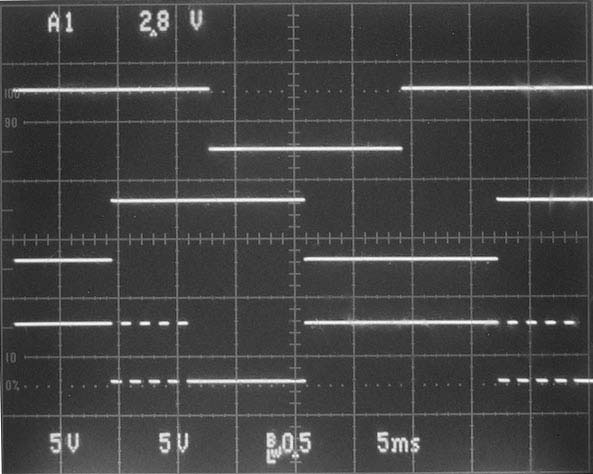
If the encoder is rotated fairly quickly, the period of signal B reduces accordingly until the width of the low portion of the signal (the 'space') is just less than tW (the duration of IC3a's output pulse). Since Q at pin 13 is now high when signal B goes high, IC2b's flip-flop is clocked by B's rising edge and its Q output at pin 9 goes high. This low-to-high transition releases IC3b from its reset state and simultaneously triggers the astable which starts to oscillate at a frequency determined by R6-C4 and R8-C5. Consequently, one or more pulses appearing at IC3b's /Q output are gated through IC1d in addition to the pulse from IC3a's Q output. This can be seen in the bottom trace of Figure 2a.
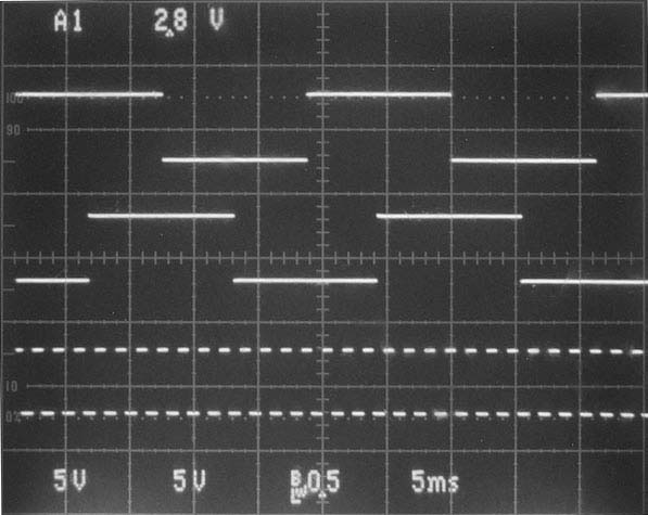
Ultimately, when the encoder is rotated very quickly, the low-going edge at B retriggers IC3a before its Q output has a chance to go low. Under these conditions, the Q outputs of IC3a and IC2b are both constantly high, thus allowing the astable to free-run. The resulting signal at IC1c's output is a train of pulses at the astable frequency as shown in the bottom trace of Figure 2b.
|
|||||||||
| Figure 2 details | Top trace: Signal A; Middle trace: Signal B; Bottom trace: Circuit output at IC1c. | ||||||||
The point at which the circuit changes from single pulsing to multiple pulsing is determined by IC3a's timing components. The fastest rate that a user could reasonably be expected to rotate an encoder is around two revolutions per second. For an encoder with 20 increments per revolution, this is equivalent to 40 pulses per second, or a signal period of 25 ms. Therefore, when the encoder is rotated faster than two revolutions per second, the circuit transitions to generating multiple output pulses.
The astable frequency should be chosen to suit your requirements. With the values of R6, C4, R8, and C5 as shown in Figure 1, the astable frequency is around 600 Hz and the pulse width is nominally 1 ms. Note that for the circuit to work properly, IC3a must be a retriggerable monostable. Normally, IC1c is connected to act as an inverter by connecting its unused input high. However, by connecting this input to IC2a's Q output, the circuit generates output pulses only when the encoder is rotating in a clockwise direction; conversely, by connecting the NAND input to IC2a's /Q output, the circuit generates output pulses only for counterclockwise rotation. This kind of behaviour may be useful where you need to generate output pulses only when the encoder is rotated in a particular direction.
