Editor's Note
This unusual circuit could be placed in the PLL/FLL family, but it's neither. At its heart, it's a self-adjusting monostable that will convert digital signals over a 5:1 frequency range to accurate square waves.
In applications where you need a pulse output with a 50% duty cycle, you can use the circuit below. There are similar circuits in the literature [References 1, 2, 3], but they require adjustments or selection of some components to set the duty cycle to 50%. This circuit produces a 50% duty cycle pulse output without the use of a setup adjustment.
The output of a divide-by-2 circuit is RC filtered to provide a dc reference for the feedback loop, which automatically maintains the duty cycle of the output pulse at 50%. Both the divide-by-2 output and the final output are passed through inverters on the same IC chip; therefore their DC components will be closely matched for comparison. The circuit has been tested from 2.5MHz to 12.5MHz. 74HC parts (instead of 74AHC parts) will work to at least 5MHz. The circuit will work at lower frequencies if the values of the ramp capacitor, C2, and the RC filter are suitably adjusted for the desired frequency range. The value for C2 can be calculated from: C2 = 588/f, in pF, for f in MHz (mid-frequency). This equation assumes the ΔV of the ramp is 1.70V. The ΔV of the ramp is greater at higher frequencies because of the delay through the discharge circuit, therefore the equation is less accurate at higher frequencies, but it will give a good starting value. Note that the values of R5, R7, C4, and C5 in the RC filter at the input of amplifier U4a, and the values of R8, R10, R11, C8, and C9 associated with amplifier U4b, affect loop stability.
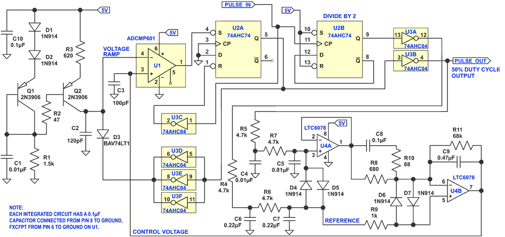
The heart of the circuit is a pulse width modulator, which is controlled by feedback from amplifier U4b. Q1, Q2, and associated circuitry provide a constant 2mA current to charge capacitor C2. This provides a voltage ramp at pin 4 of U1, an ultra-fast comparator. When the amplitude of the voltage ramp exceeds the voltage at pin 3 of the comparator, the output of the comparator goes low, and sets the flip-flop U2a. The Q output goes high, and causes the paralleled inverters U3d-f to discharge the ramp capacitor C2 through diode D3. The BAV74LT1 was used for D3 because its low capacitance avoids causing a voltage step on C2 when its cathode is pulled high at the beginning of the next voltage ramp.
The output of the divide-by-2 flip-flop U2b is passed through inverter U3a, and is then filtered to provide the DC reference for amplifier U4b. This amplifier compares the filtered voltage derived from the output square wave to the reference voltage, and adjusts the control voltage fed back to the comparator to maintain the duty cycle of the output signal at 50%.
A precision op amp with low input offset voltage is used for U4, because the offset is multiplied by U4b, which causes an error in the duty cycle of the output. The input offset voltage of the LTC6078 small enough to be insignificant, but it is a consideration if you want to use a different chip. Diodes D4 through D6 provide controlled start-up of the op amps and allow the steady state condition to be reached more quickly. Also, SPICE simulations showed that they reduce the stress on some components during start-up. Similarly, R2 and C1 reduce the stress on Q1 and Q2. For best results, the output should be lightly loaded to avoid distortion of the signal, which may change its DC level, and therefore its duty cycle.
The duty cycle of the input pulse must be less than 50%. If it is greater than 50%, either reduce the duty cycle, or pass it through an inverter before applying it to the input of the circuit.
References
- Wide-range pulse-shaping circuit gives square waves with 50% duty cycle
- R. M. Stitt and R. L. Morrison, Burr-Brown Research Corp., International Airport Industrial Park, Tucson, Ariz.
- 400 Ideas for Design volume 3, 1976, page 178.
- One-shot with feedback loop maintains constant duty cycle
- H. P. D. Lanyon, Worcester Polytechnic Institute, Worcester, Mass.
- Electronics Designer’s Casebook, page 122. (No volume number or published date given.)
- Frequency-doubler produces square-wave output
- Robert L. Taylor, I & F Electronics, Nashville, Tenn.
- Electronics Designer’s Casebook Number 1, page 23. (No published date given.)
