James Campbell
Electronic Design
This relatively simple circuit uses a 6-V DC supply with a PWM current-source configuration to provide efficient, adjustable dimming of a white LED over a wide range, needed to accommodate the unique lighting needs of an optical microscope over its magnification range from 40× to 1000×
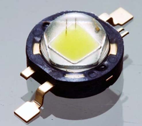
When the built-in incandescent light source of my venerable Olympus microscope failed after many years of use, I decided to design a reliable modern replacement. A 1-W white LED (SEOUL X42182, 350 mA max, VF = 3.25 V) was the obvious choice to provide high brightness and full-spectrum light without the heat of incandescent or xenon arc lamps (Figure 1). The microscope lamp brightness needs to be adjustable, however, to accommodate the different objective lenses, which offer magnifications from 40× to 1000×.
 |
|
| Figure 1. | The white LED SEOUL X42182. |
This simple circuit allows full-range dimming by driving the LED with a stable current source while generating little heat (see the Figure 2). Shunt voltage regulator Q2 sets a stable 2.5-V reference that is divided by R1 and R2 to give a maximum voltage of 0.66 V at the top of R2. Different values of R1 and R2 may be used as long as the sum of their values is greater than 20 kΩ, to keep Q2 in regulation.
 |
|
| Figure 2. | This circuit provides adjustable dimming of the white LED over a wide range, a requirement for the microscope application with its settable magnifications. It takes what appears to be a linear current source and uses it in a PWM mode. |
As the nominal end-to-end resistance of potentiometers may have wide tolerances, measure the value of R2 that you are using and then calculate R1 to provide the 0.66-V maximum voltage at the non-inverting input of U1.
The inverting input of U1 monitors the voltage generated by the current through R4 and sets that voltage to match the voltage at the potentiometer wiper. The current through R4 must pass through the LED and Q1. Although this circuit appears to be a linear current source, the combined gain of U1 and Q1 is so high that the op amp operates in pulse-width modulation (PWM) mode, running at about 100 kHz. R5 and C4 create a 12.5-kHz low-pass filter, reducing any ripple of the current through the LED to less than 1%. The circuit thus creates a stable and fully adjustable light source without discernible flicker.
The LED requires a 1-W heatsink, which may also be used for the mechanical mounting to hold the LED rigidly in place in the optical axis of the microscope, as the LED must not jiggle if the microscope is touched or adjusted. Q1 also needs a small heatsink as it generates about 0.75 W of heat at full brightness, while R4 produces only 0.25 W of heat and barely gets warm.
Any 6-V isolated dc supply capable of providing 400 mA or more can be used for powering the circuit. Commercial wall-plug switching supplies are available and work well here. For certain medical or laboratory use, though, voltage isolation and leakage-current specifications of the supply might have to meet special standards such as IEC 60601.