I’ve just finished a little Arduino project. It’s a shield for the Arduino Uno that lets you measure inductance. This is a functionality that I found missing in just about any digital multi meter. Yes, there are specialized LCR meters that let you measure inductance but they typically won’t measure voltages or currents. So I had to build my inductance meter myself.
 |
|
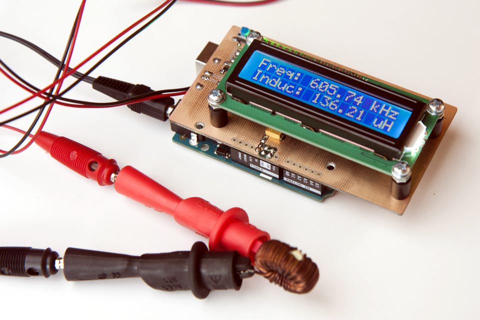
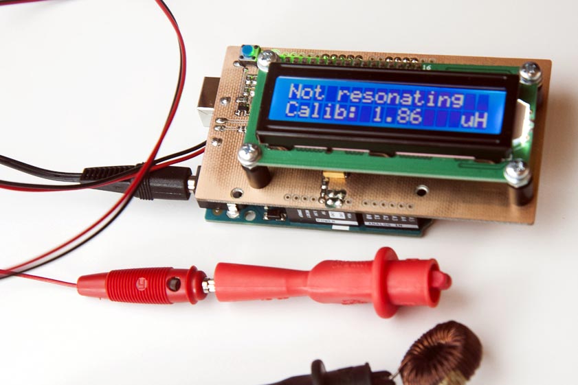
| Figure 1. | Inductance meter in action. It displays the resonance frequency together with the inductance |
The basic design is really simple (Figure 2). It a colpitts oscillator with the coil missing. You use the test leads to connect it to a coil which will make it resonate. The Arduino then measures the frequency at which the oscillator is resonating and calculates the inductance. The capacitors are part of the shield so the capacity is known. All related files (Schematic Diagram, PCB and Arduino Sketch) can be downloaded in download section.
 |
|
| Figure 2. | Arduino-based Inductance Meter Schematic Diagram. |
There is 1uH of inductance included on the schield which is placed in series with the coil to be measured. This serves two purposes: The oscillator can resonate when you short-circuit the test leads. When you then press the push button on the shield, the software will use the current measurement as new calibration (Figure 3, 4). It also puts an upper limit on the resonance frequency. This ensures that the software the rest of the circuit can keep up with the oscillator.
 |
|
| Figure 3. | Pressing this blue button zeroes the meter. |
As can be seen from the schematic, the oscillator uses two 1 nF capacitors in series. Together with the 1 uH inductance, this limits the frequency to about 7.1 MHz. In practice, it oscillates at around 5.4 MHz when the test leads are short-circuited.
 |
|
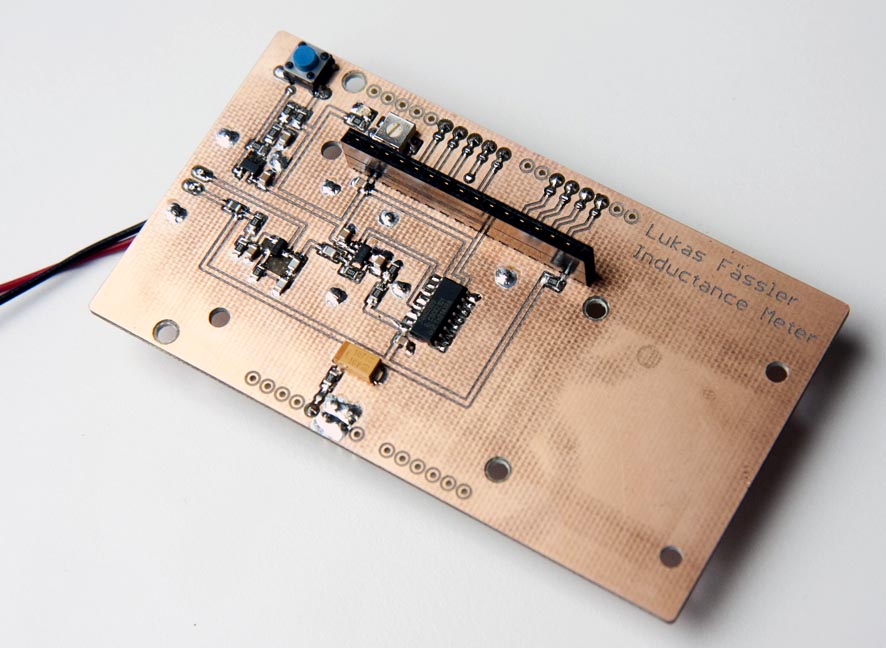
| Figure 4. | The entire shield with the display removed. |
The oscillator output is followed by a comparator turning the sine wave of the oscillator into a square wave. I’ve used an inexpensive but fast Microchip MCP6561R. It has a maximum propagation delay of 80 ns which allows it to keep up at the maximum frequency.
But of course, 5.4 MHz is way too fast for the Arduino to keep up. The Arduino runs at 16 MHz and will need at least a few dozend instructions to process each pulse from the shield. My solution was to add a 74HC590 8-bit binary counter dividing the frequency by 256. That gives a theoretical maximum frequency of 7.1 MHz / 256 = 27.7 kHz. That’s something the Arduino can deal with.
 |
|
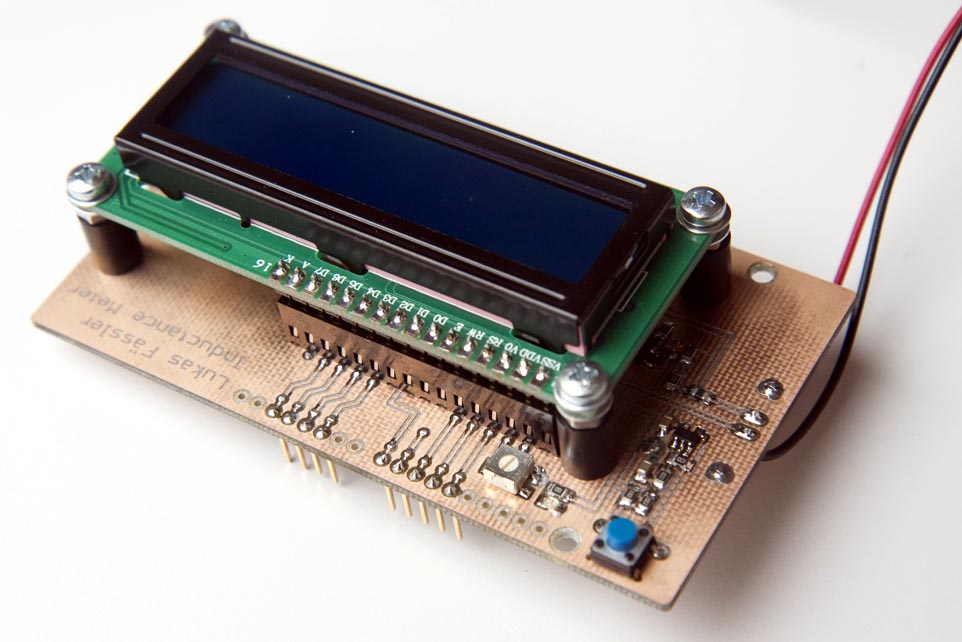
| Figure 5. | With the test leads open, the oscillator can’t resonate. The currentcalibration/zero-offset is displayed in stead. |
For obvious reasons, there is also a display included on the shield. And then there’s that pushbutton which is debounced in hardware by running it through an RC low-pass filter and a Schmitt-triggered buffer. The button is used to zero the meter, i.e. the current measurement is used as the new zero-offset. With the test leads open, the oscillator can’t resonate. The current calibration/zero-offset is displayed in stead (Figure 5).
| Table 1. BOM | ||||||||||||||||||||||||||||||||||||||||||||||||
|
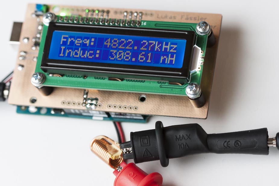
The main problem are the test leads. They have quite a bit of inductance themselves. You can zero that by pressing that button but their inductance easily varies by maybe plus/minus 100 nH depending on how you hold them. If you’re careful to calibrate them in the same position as you measure you can measure very small inductances such as the 300-something nH you see on the Figure 6. It’s just 12 turns of a wire.
 |
|
| Figure 6. | Arduino-based Inductance Meter: Even very small inductance values can be measured. |
Downloads
Arduino source code (aka sketch) as well as the Eagle files and PDFs - download
