Current models of spectrum analyzers routinely offer frequency responses that begin as low as 10 Hz. When you combine them with 1-Hz or narrower band FFT software, expanded low-frequency performance makes the modern spectrum analyzer an invaluable tool for designing and debugging high-performance analog circuits. Unfortunately, a spectrum analyzer that's primarily for RF typically presents an input impedance of 50 Ω, a heavy load when you apply it to most high-impedance analog circuits. You can improvise a somewhat higher impedance probe by adding a 953 Ω resistor in series with the 50 Ω input, but this approach provides only a 1-kΩ input impedance and reduces the measured signal by 26 dB.
In addition, most RF-spectrum analyzers lack ac coupling, and, thus, any dc-input component directly reaches either the internal terminating resistor or the front-end mixer. To maintain a 10-Hz, low-frequency response, you must connect a coupling capacitor with a value of at least 2 µF in series with the 953 Ω input probe. Although oscilloscopes' input circuits can withstand accidental probe contacts and capacitive-transient overloads, using a low-impedance, ac-coupled probe with a spectrum analyzer can lead to destruction of the analyzer's expensive and possibly hard-to-replace front-end mixer.
Although high-impedance probes are commercially available, they're expensive to purchase and repair. This Design Idea offers an alternative: an inexpensive and well-protected unity-gain probe that presents the same input impedance as a basic bench oscilloscope and can drive the spectrum analyzer's 50 Ω input impedance. The probe has a gain of 0±0.2 dB at 100 kHz. Input impedance is 1 MΩ, 15 pF, and maximum input is 0.8 V p-p. Load impedance is 50 Ω, and frequency response is 10 Hz to 200 MHz at –3 dB. Passband ripple is less than 1 dB p-p. Input noise at 1 MHz is less than 10 nV/√Hz. Distortion for 0.5 V p-p input at 10 MHz is less than –75 dBc for second-order distortion and less than –85 dBc for third order. Power requirements are ±5 V at 16 mA.
You can assemble the circuit in Figure 1 in an afternoon from readily available and inexpensive components. The circuit's input presents the same characteristics as a bench oscilloscope – a 1-MΩ resistance in parallel with 15 pF of capacitance. You can also use this active probe in place of standard 1-to-1 or 10-to-1 oscilloscope probes, thus extending the design's applicability. The back-to-back silicon diodes in the D1 clamp the input signal to plus or minus one forward-voltage drop, which limits signal excursions you apply to the spectrum analyzer's front end, thus protecting the input mixer from damage due to overloads and ESD. Because most users employ the probe and spectrum analyzer to measure small-amplitude signals and noise, the limited large-signal response does not affect most applications.
 |
|
| Figure 1. | Just a handful of parts can help extend a spectrum analyzer’s performance. This unity-gain probe emulates a standard oscilloscope probe’s 1-MΩ and 15-pF input characteristics and easily drives 50 Ω loads. |
High-performance FET input operational amplifier IC1, a Texas Instruments OPA656, provides a voltage gain of two. This configuration yields a bandwidth of approximately 200 MHz (Figure 2). The OPA656 can drive 50 Ω back-matched loads for a total load of 100 Ω, which results in a 6-dB gain loss for which IC1's gain of two compensates for a net gain of unity. The OPA656 also introduces lower noise and distortion than that of most commercially available, active FET-based probes.
 |
|
| Figure 2. | The probe’s measured –3-dB frequency response extends from 10 Hz to 200 MHz with slightly less than 1-dB passband ripple, which compares favorably with the ±2-dB response of many commercial active-FET probes. |
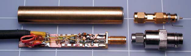
The probe in Figure 3 fits into a small section of brass hobby tubing. The input connector comprises a small SMA edge-launch connector that you can easily adapt to other connectors, including the BNC and its many accessories.
 |
|
| Figure 3. | You can assemble the probe on a piece of breadboard that fits into a section of brass tubing from model and hobby shops. An SMA input connector matches a multitude of adapters and probe tips, a few of which are shown. Use a rubber grommet to close the probe’s output end. |
The probe requires 5 and –5 V at approximately 18 mA each, which you can obtain from an instrument's probe-power connector if available or from a linear supply designed around an ac wall transformer. For best results, use 78L05 and 79L05 voltage regulators to stabilize the supply voltages.
Standard miniature 50 Ω coaxial cable connects the probe to the measuring instrument. For the flattest frequency response and uniform gain, terminate the probe's output with 50 Ω; the circuit requires no dc-output-blocking capacitor.
Materials on the topic
