Ioan Ciascai
EDN

Reading quadrature encoder signals at high speeds (e.g., 1 MHz, or, 1 m/s with a resolution of 1 μm) often requires dedicated hardware. This Design Idea shows a simple scheme to accomplish this function using only an ATtiny2313A AVR microcontroller. Of course, the microcontroller can also be connected to other devices via the serial interface, or the measured position can be displayed on a local LCD, which could be connected to port PB. Additionally, one or more LEDs can be added to signal error conditions.
 |
|
| Figure 1. | Reading quadrature signals with ATtiny2313A; the Z index signal is optional. |
In this implementation, the interrupt handler is very important. It reads input signals A and B in less than 1 μs. Differential signals AP/N and BP/N are processed by SN75157 receivers, unneeded if your encoder outputs logic-level signals.
The processor is configured to generate an interrupt for any change of port PD pins. This interrupt is the last in the table of interrupt vectors, and hence can dispense with the jump instruction, resulting in a reduction in the interrupt service time of 2-3 clocks (100-150 ns).
An XOR operation between previous and current signals (AOLD ⊕ BNEW or ANEW ⊕ BOLD) determines if the current position has incremented or decremented from the previous. AOLD and BOLD are the A and B signals before changing state, and ANEW and BNEW are the values after the interrupt. The interrupt handler is in the PCIsubroutine1.txt file.
The execution time of the interrupt handler is 800-850 ns (16-17 clocks). To minimize the execution time of the ISR, some registers have been dedicated to it and must not be used by the main program:
- R10 to save SREG and test for activation of new interrupt
- R11 and R12 for the new and old states
- R24 and R25 for position transducer
To calculate the current position requires only one clock cycle. The downside is that the position can only have 65536 values. You can determine the position using 3 or 4 bytes, in which case the subroutine execution time increases to 18-19 cycles from adding the necessary instructions (use the register pair R24, R26, R28, or R30).
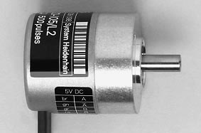
The interrupt handler checks for a new interrupt before exiting the current ISR. This case is signaled by setting bit T in SREG. Implementing this check, the execution time increases by 3 cycles. We have tested the operation of the subroutine using an RB6029 (4,000 pulses per rotation) at maximum speed, with no errors detected.
Before activating interrupts, the PCIE2 value must be placed in register R12 (read PIND register before enabling PCINT2 interrupt and SREG – I flag is set).
If you want to use the Z index signal, the position will be stored in three registers as 1,024,000 values (4,000 counts/rotation; 256 rotations). The interrupt handler to read the data is more complex, as seen in PCIsubroutine2.txt. Length is 19 cycles, or 20 cycles when the current position is incremented when Z is active.
If the Z index is active, we clear the angular position, increment the revolution count, and check that the previous angular value was 3,999. In this subroutine, three errors are detected: one for an overlapping new interrupt (as in the previous case), and two related to the Z index (checking the correctness of the previous angular position). Error counter registers rerr1, rerr2 and rerr3 should be defined by the user. To initialize the system, run InitIndexZ.txt, which waits for Z to be active.
