Shyam Sunder Tiwari
Electronic Design
 |
Ambient light is increasingly being used as a source of energy. To help designers of such systems, this circuit accurately measures ambient light intensity over four decades of measurement. The design is highly cost effective and, with the sensor mounted in a waterproof glass enclosure, can be deployed in the field for continuous monitoring in all weather conditions.
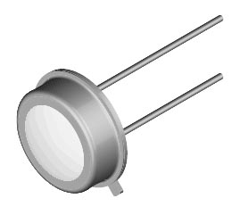
The sensor in this application, a BPW21R photocell (from Vishay), is used to generate photocurrent proportional to the ambient light intensity (see Figure 1). A photovoltage measurement technique would not offer the high dynamic range desired.
The LMC555 CMOS timer converts the photocurrent from the BPW21R into a transistor-transistor-level (TTL) frequency source (10 Hz to 100 kHz). Any other equivalent timer IC can also be used, but component quality is very important in order to get high dynamic range with accurate measurements. Capacitor C1 should be an NPO/COG or X7R type. NPO/COG capacitors have the lowest temperature coefficient and minimize frequency drift with temperature. C2 is a filter capacitor for the comparator voltage references.
 |
|
| Figure 1. | This circuit offers a cost-effective way to measure ambient light by converting the current output from a photocell to a frequency that can be measured at a remote location. |
C1 and resistor R1 are timing elements. While charging time depends on the photocurrent from the BPW21R and the value of C1, the discharge time for C1 depends on its capacitance and the resistance of R1. Since both charging time and discharge time contribute to the output’s frequency, it’s important to select R1 to keep the discharge time as low as possible. In this case, R1 is 1 kΩ and C1 is 1 nF, making the discharge time 1 µs.
The photocell’s dark current is about 2 nA and its maximum output is about 60 µA at saturation level. The cell’s linear sensitivity is 9 nA/lx or 9 µA/klx. This high dynamic range allows the photocell to operate from 10 nA to 50 µA easily.
The high-level pulse width (TH) is inversely proportional to the light intensity and can be used for very accurate measurements. The low-level pulse width (TL) remains constant and isn’t significantly affected by the photocurrent unless R1 is greater than 100 kΩ. R1’s value can be selected according to the application and the detection capability of the frequency-measuring device.
As noted earlier, an R1 of 1 kΩ is ideal for a fast measurement device. For slow measurement devices, like a microcontroller, R1 can be as high as 100 kΩ. Increasing the value of R1 reduces the circuit’s linearity at high photocell currents, because TL becomes comparable to TH.
However, if the measurement technique uses only TH, R1 can be as high as 100 kΩ without affecting measurement accuracy. If R1 is larger than 100 kΩ, the voltage drop increases across the resistance and the voltage decreases across the photocell. This causes the photocell to operate in a nonlinear region, which is undesirable. Therefore, the best range for R1 is from 1 kΩ to 100 kΩ. Resistor R2 is 50 Ω, which is suitable for driving the output signal over several hundred meters of RG58 coaxial cable to a remote measurement room.
An important advantage to this circuit is that the power source can range from 5 V to 12 V without seriously affecting its operation. That and the circuit’s very low current draw allow the design to operate off a standard 9-V battery.
