Sajjad Haidar
EDN
A simple blocking oscillator circuit can be used to step up voltage using properties of coil inductance (V = L di/dt). Such a circuit is shown in Figure 1, which is more commonly called a Joule thief.
 |
||
| Figure 1. | Basic Joule Thief circuit. | |
The output will be pulses of voltage that can be filtered using a diode and capacitor. As there is no regulation, the output voltage will vary with the input voltage or load. As this circuit uses a BJT, the supply voltage needs to be at least 0.7 V to work, and with enhancement-mode MOSFETs, the supply voltage must usually be even higher.
In this Design Idea, a low-threshold MOSFET (Q1) is used with coupled coils L1 and L2 to act as a Joule thief circuit (Figure 2).
 |
||
| Figure 2. | MOSFET-based Joule Thief. | |
A toroidal ferrite core is used to make the coupled coil or transformer. A photovoltaic optocoupler, TLP191B, is used to circumvent the problem with the threshold voltage. Part of the output is used to power TLP191B to make an isolated voltage source in series with the gate of Q1 (AOI508). This isolated voltage can be controlled by the pot R5; capacitor C1 is used to pass the pulses produced by L1 to the gate for switching.
For regulation, another MOSFET, Q2 (IRLU3103), is used. The threshold voltage of Q2 is used to regulate the output voltage. When the output reaches 5 V, the divider formed by R1 and R2 makes Q2 conduct, and the oscillation ceases, causing the output voltage to drop. As the threshold voltage is not very sharp, the regulation is not usually that good.
To start working, the circuit initially needs higher voltage than the VTH of Q1. At 1.9 V, the circuit oscillates, and the output voltage is 5.1 V. As the input voltage goes down, the oscillator stops at 1.4 V. By adjusting pot R5 to higher values, the minimum operating voltage can go as low as 0.6 V. The input-output voltages are shown graphically in Figure 3.
 |
||
| Figure 3. | VIN vs. VOUT. | |
Efficiency drops at lower input voltages. The efficiency for VIN = 2.5 V is 48% and goes down to 36% at 0.6 V.
 |
||
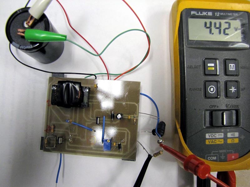
| Figure 4. | The built circuit. | |
In my application, the circuit is connected to a supercapacitor of 150 F @ 2.5 V, which is charged up to 2.3 V. The charged capacitor powers the load (470 Ω) for 38 minutes, until its voltage reaches 0.6 V. The implemented circuit with the supercapacitor connected is shown in Figure 4.
Note:
In [1], a circuit is shown with a JFET or depletion-mode MOSFET, which will work as a DC to DC converter with an input voltage as low as 0.1 V. Simulation results show that its efficiency is very poor. Most of the power will be wasted by the FET and the source resistance.
