Fons Janssen, Maxim Integrated
EDN
Introduction
High-capacity, multilayer ceramic capacitors (MLCC) have a property often not well understood by electronic designers: the capacitance of these devices varies with applied DC voltage. This phenomenon is present in all high-dielectric constant, or Class II capacitors (B/X5R R/X7R, and F/Y5V characteristic). However, the amount of variation can differ considerably among different MLCC types. A good article on this topic was written by Mark Fortunato.[1]
The conclusion of this article is that you should always check the capacitor’s datasheet to see how the capacitance varies with the bias voltage. But what if the datasheet does not include this information? How can you determine how much capacitance is lost under the conditions in your application?
Theory for Characterizing Capacitance versus Bias Voltage
A circuit to measure the DC bias characteristic is shown in Figure 1.
 |
||
| Figure 1. | Circuit to characterize capacitance versus bias voltage. | |
This circuit is built around op amp, U1 (MAX4130). The op amp acts as a comparator, with feedback resistors R2 and R3 adding hysteresis. D1 sets a threshold above GND so that no negative supply voltage is needed. C1 and R1 form a feedback network to the negative input, which makes the circuit operate as an RC oscillator. Capacitor C1, the device under test (DUT), serves as the C in this RC oscillator; potentiometer R1 is the R.
The voltage waveforms of the op amp output pin, VY, and the junction between R and C, VX, are shown in Figure 2. When the output of the op amp is at 5 V, capacitor C1 is charged by R1 until it reaches the upper threshold. This forces the output to 0 V. Now the capacitor is discharged until VX reaches the lower threshold, thus forcing the output back to 5 V. This process repeats, resulting in a stable oscillation.
 |
||
| Figure 2. | Oscillation voltages VX and VY. | |
The oscillation period depends on the values of R, C, and the upper and lower thresholds VUP and VLO:
Since 5 V, VUP, and VLO are constant, then T1 and T2 are proportional to RC. (This is often referred to as the RC time constant.)
The threshold of the comparator is a function of VY, R2, R3, and the forward voltage of D1 (VD):
Where VUP is the threshold for VY = 5 V, and VLO is the threshold for VY = 0 V. With the given values these thresholds yield to approximately 0.55 V for VLO, and 1.00 V for VUP.
The circuit around Q1 and Q2 converts the cycle time into a proportional voltage. This works as follows. MOSFET Q1 is controlled by the output of U1. During T1, Q1 is on, clamping the voltage on C3 to GND. During T2, Q1 is off, allowing the constant current source (Q2, R5, R6, and R7) to linearly charge C3.[1] As T2 is increased, the voltage on C3 becomes higher. Figure 3 shows the voltage on C3 over three cycles.
 |
||
| Figure 3. | C3 is clamped to GND during T1 and linearly charged during T2. | |
The average voltage on C3 (VC3) is equal to:
Since I, C3, α, and β are all constant, the average voltage on C3 is proportional to T2 and, therefore, also to C1.
Lowpass filter R8/C4 filters the signal while low-offset op amp U2 (MAX9620) buffers the output so that it can be measured with any voltmeter.
Before measurements can be made, this circuit requires a simple calibration. First the DUT is installed in the circuit, and VBIAS is set to 0.78 V (the average of VLO and VUP) so the actual average (DC) voltage across the DUT is 0 V. The output voltage will vary when potentiometer R1 is varied. Adjust R1 until the output voltage reads 1.00 V. Under these conditions, the peak voltage on C3 is around 2.35 V.[2] The bias voltage can be modified and the output voltage will show the resultant percentage change in the capacitance. For example, if the output voltage is 0.80 V, the capacitance at that particular bias voltage is 80% of the capacitance at 0 V bias.
Lab Tests Confirm the Theory
 |
||
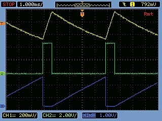
| Figure 4. | Measurement with VBIAS = 0 V; Ch1 = VX; Ch2 = VY; Ch3 = VC3. R1 was adjusted so the voltmeter showed 1.000 V.. |
|
The Figure 1 circuit was built on a small PCB. The first measurement was done using a random 10 µF capacitor. Figure 4 and Figure 5 show the signals under 0 V and 5 V bias conditions, respectively.
 |
||
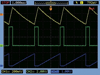
| Figure 5. | Measurement with VBIAS = 5 V. The oscillation period has clearly decreased due to the reduced capacitance. Ch1 = VX; Ch2 = VY; Ch3 = VC3. The voltmeter reads 0.671 V. |
|
At 0 V bias, potentiometer R1 was adjusted so the voltmeter showed 1.000 V. At 5 V bias, the voltmeter showed 0.671 V, indicating that 67.1% of the capacitance remained. With an accurate counter, the total period, T, was also measured. T was 4933 µs at 0 V bias and 3278 µs at 5 V, indicating that 66.5% (= 3278 µs/4933 µs) of the capacitance remained. These values match very well, demonstrating that the circuit design can accurately measure the capacitance drop as a function of the bias voltage.
 |
||
| Figure 6. | Relative capacity as a function of bias voltage for a 2.2 µF/16 V MLCC. The values are normalized to the capacitance at 0 V bias. The blue curve is based on measuring the output voltage of the circuit; the red curve is based on the measurement of the oscillation period; the green curve is based on characterization data supplied by the Murata Simsurfing tool. |
|
A second measurement was performed, now using a known 2.2 µF/16 V capacitor taken from a sample kit supplied by Murata (part number = GRM188R61C225KE15). In this measurement the values were recorded over the entire operating 0 V to 16 V range. The relative capacitance was determined by measuring both the output voltage of the circuit and the actual oscillation period. Additionally, data was collected from the Murata® Simsurfing tool, which can provide the DC bias characteristic for this particular part based on measurements performed by Murata. Figure 6 shows all the results. Both graphs with our measurement data show almost identical results, which proves that the time-to-voltage circuit performs well over a larger dynamic range. There is some difference between the data from the Simsurfing tool and our measurements, but the shapes of the curves are similar.
Conclusion
Using the presented circuit, a dual power supply, and a voltmeter it is quite simple to measure the DC bias characteristic of a high-capacity MLCC. A quick bench test will reveal how much the capacitance decreases as a result of the applied bias voltage.
Reference
Materials on the topic
Footnotes
- This will only be linear when using a capacitor with constant capacitance up to 5 V bias voltage (MKS, MKT, etc).
- To prevent saturation of Q2, the voltage peak on the collector (= VC3) should stay below the emitter voltage minus the emitter-collector saturation voltage, which yields to approximately 4 V.
