Understanding Raspberry Pi Inputs
Push Button Switch Input
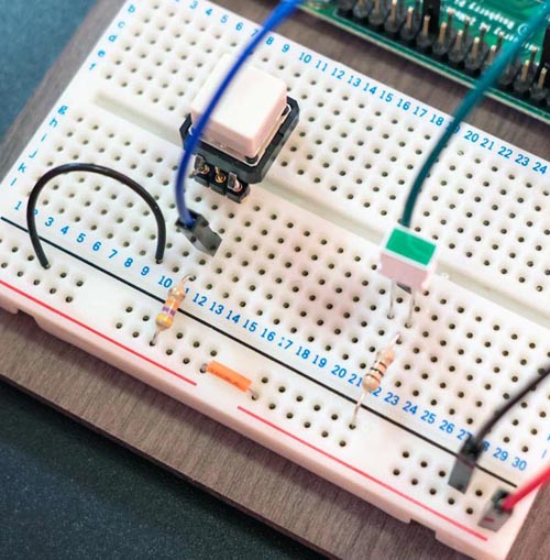
The connections on the Raspberry Pi can be converted into inputs under software control. The example here is about the simplest; a push button switch is wired up to the 40-pin connector (Figure 11).
 |
||
| Figure 11. | Push button switch is wired up to the 40-pin connector. | |
The circuit diagram is shown below (Figure 12). Note that the LED circuit from the exercises before is still left wired up but is not shown in the diagram below.
 |
||
| Figure 12. | Schematic diagram for connecting push button to RPi. |
|
As can be seen from the circuit diagram, when the switch is not pressed the input pin is connected to +3.3 V through a resistor. The input pin has a high resistance inside the Raspberry Pi, and so the voltage at the input pin is close to the 3.3 V that the resistor is connected to. This means that the Raspberry Pi will detect a logic ‘1’ condition when the switch is not pressed.
When the switch is pressed, there is a direct path between the input pin and 0 V and so the voltage at the input pin becomes 0 V which is a logic ‘0’ condition.
For this simple switch circuit, the value of resistor R1 is not critical and can be any resistance from around 1k to 47k, but avoid low values since that increases current consumption when the switch is pressed.
Here is some example Python code that can detect the push button switch status (file Listing_4(Button).txt in download section). To use the code, save the code in a file called button-test.py and then to run it type:
sudo python button-test.py.
The code displays the button status on the screen, along with a count of how many times the button was pressed. You’ll notice that occasionally the count increases more than the number of times the button was thought to be pressed and this happens because of ‘contact bounce’; as the switch is pressed, the contacts connect together and release many times rapidly before finally making contact. A similar thing happens when the switch is released. The solution is to have ‘debouncing’ functionality. It can be implemented in hardware or in software (the software method is very common). The code (file Listing_5(Button_Debounce).txt) implements debouncing and will more accurately register the correct number of button presses. The only difference with the earlier code is that this time the input status is checked a second time delayed by about 20 msec – this provides time for contact bounce to have completed.
Another Input Example: A Voltmeter
The Raspberry Pi has digital inputs and outputs but the real world has analog quantities that may need to be measured or controlled. The example here converts analog values into a digital signal that can be read using a Raspberry Pi input connection.
 |
||
| Figure 13. | Schematic diagram: Voltmeter for RPi | |
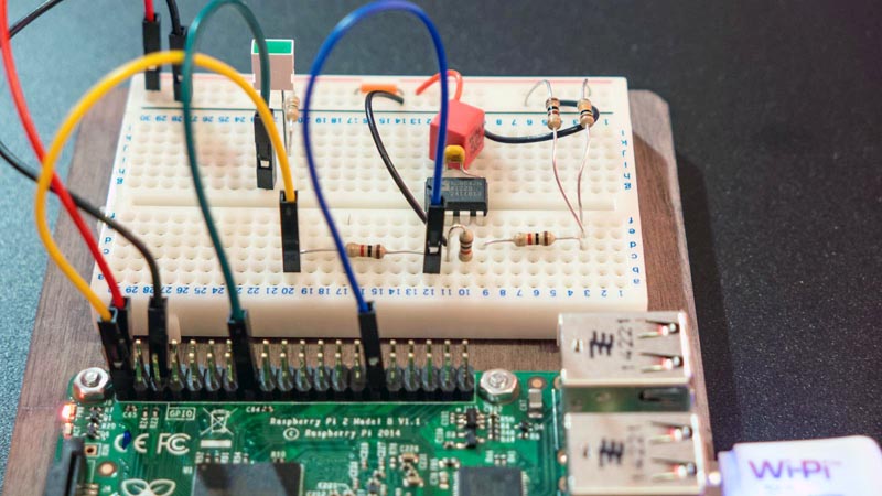
The example is an extremely simple voltmeter (Figure 13, 14); it can measure voltages between 0 and 1 V with good precision. Note that this won’t replace a handheld multimeter! It doesn’t have the requisite safety protection and could damage itself or persons or property if used for anything beyond the scope of the examples described here.
 |
||
| Figure 14. | Voltmeter circuit on bread board. | |
The circuit uses an AD654 integrated circuit which generates a square wave with frequency dependant on an input voltage. The square wave output is connected to a Raspberry Pi input (GPIO5 in this example). The square wave has a frequency of up to 10 kHz and so some accurate timing is needed to determine the voltmeter input. The code (file Listing_6(Voltmeter).txt) uses the C programming language and a library called wiringpi written by Gordon Henderson. First off, install the wiringpi library:
mkdir development
cd development
git clone git://git.drogon.net/wiringPi
cd wiringPi
./build
Next, save the following code into a file called voltmeter.c. The code can be compiled by typing:
gcc -o voltmeter -lrt -lwiringPi voltmeter.c
To run the code, type:
sudo ./voltmeter
The code uses an averaging method to get high precision. It rapidly measures the width of the incoming square wave 64 times, and then sums the values and divides by 64 to get the average value. Then it sleeps for a second to allow other processes to do their thing, and then repeats.
The circuit also needs a few things for high precision. The 10 nF timing capacitor for the AD564 is selected to be a polypropylene part for better accuracy. The 1 k timing resistor can be a 1% part or alternatively a variable trimming resistor can be used. The circuit runs from the 5 V supply from the Raspberry Pi 40-pin connector but this is only approximately 5 V and so the circuit would benefit from a dedicated and more accurate 5 V supply circuit.
As a quick check, the circuit shown above had the voltmeter input subjected to a potential divider circuit consisting of two resistors. The calculated voltage (if the resistors were precisely the correct values and the supply was exactly 5 V) out of the potential divider is 0.04950 V. When the software was run, it reported measurements of 0.04991V in the short test. Not bad for such a simple project!
Diodes D1 and D2 in the circuit above are optional but highly recommended because they will provide some protection to the integrated circuit if the input is accidentally subjected to a voltage outside the 0-1V range.
Input Design Tips
Protected Inputs
The Raspberry Pi can be protected from accidental connections to higher than expected voltages by adding an additional circuit to the inputs in use. A very good option in some situations is to use an optocoupler alternatively a low-cost method such as the circuit below will tolerate voltages as high as 60 V without damaging the Raspberry Pi, and will cope with reversed connections too (Figure 15). The BC547B transistor in the circuit can be replaced with another type such as 2N3904 or BC549 if more convenient to obtain. R1 can be a (normal) 0.25 W resistor for inputs up to around 50 V, and will need to be a 0.5 W part otherwise.
 |
||
| Figure 15. | Additional circuit for protecting RPi digital inputs. | |
The output of this circuit is inverted, and an input voltage higher than about 2 V will pull the output low.
Connecting to 5 V Logic
A direct connection of a 5 V logic output to a Raspberry Pi input could cause damage. Different approaches can be taken depending on the specific need.
If the 5 V logic output changes slowly then you could consider using a potential divider circuit (i.e. two resistors) but it is not a great method (it doesn’t work for fast circuits). A far better method is to use a 5 V tolerant buffer integrated circuit. A mid-way approach adequate for up to 100 kHz switching speed is shown below (Figure 16), using a ZVN2110A N-channel MOSFET. The output is inverted.
 |
||
| Figure 16. | Simply Logic Level Converter circuit. | |
Alternative MOSFETs that are suitable include ZVNL120A and VN10LP.
MOSFETs are easy to damage when unsoldered in a circuit due to a very delicate gate structure (it is made of a thin layer internally that can be destroyed with high voltage). Take electrostatic precautions and another good practice is to first connect R3 into your circuit (either on a circuit board or breadboard) and then remove the MOSFET from its safe packaging and connect it into the circuit. The resistor R3 will provide some protection.
Advanced Topic: Speed and Jitter
Button-presses and LED outputs are slow events measured in tens or hundreds of milliseconds. Sometimes much higher speed signals are encountered. For example, a TV remote emits infra-red light pulses around 40k times per second. Although the core CPU in the Raspberry Pi runs at speeds approaching 1 GHz, input and output signals at that rate are not supported for several reasons that are hardware, electrical and software related. We will consider some of the software factors for the scope of this blog post.
The Raspberry Pi runs Linux which is a multi-tasking OS. It can (at any time) pre-emptively take control away from your software program in order to service other tasks. It all happens relatively quickly, so it looks like the mouse still works while your program is running, but really the Linux OS is providing short time-slices to your program and to the mouse driver code.
Ordinarily this doesn’t matter, but when you need short or high precision events this can become an issue revealed (for example) as jitter.
Furthermore choice of programming language has an effect too, because some libraries are more suitable than others. Interpreted code may run at a different speed compared to compiled code. In short if very precise timing is needed then either a Linux driver needs to be written or external hardware (such as another microcontroller, or logic circuits and clock) may be needed.
One good question for more advanced use of the Raspberry Pi capabilities is approximately how fast can output signals be toggled using the Python and C libraries and the script method described earlier?
To find out, code was written to repeatedly toggle an output pin and an oscilloscope was connected up. The results are shown below (Table 1).
| Table 1. | Output signals toggle speed when using Puthon, C and Shell Script |
||||||||||||||||
|
|||||||||||||||||
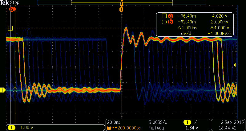
However, it is always important to remember there is jitter that will be present due to the use of the Linux OS. This is not an issue for general LED toggling of course. The oscilloscope capture below shows part of the nature of the jitter by overlaying multiple traces triggered at the same time (Figure 17). Notice that the jitter can take on many values, although they are all discretely spaced 4 nsec apart (250 MHz) which is due to internal hardware inside the Raspberry Pi.
 |
||
| Figure 17. | Jitter will be present due to the use of the Linux OS. | |
Summary
If you've read this far then by now it should be clear that the 40-pin connector on the Raspberry Pi can be used for many diverse projects from driving LEDs and relays to creating voltmeters or generating alarms. With little circuitry the 3.3 V logic compatible Raspberry Pi connections can interface to circuits. Using Python it is very easy to control outputs, and reading inputs is not too difficult either. For C programmers the wiringpi library makes control easy.
