Several months ago, I stumbled across an interesting article on halfbakery.com about the possibility of an alarm clock in which the alarm only sounds when the user is actually lying in bed. The idea peaked my interest a bit. Unfortunately the article was merely speculation; there was no information on how to actually create one. This seemed like an interesting concept on a number of levels. Never again would you forget to set your alarm before bed, or forget to turn it off in the morning. What’s more, this alarm would force you to get out of bed in the morning, alieviating the need for heavy snoozers to move their alarm clocks across the room.
Last week I decided to build just such an alarm. I picked up a cheap ($7) alarm clock and got right to work. For those interested, a detailed journal of my build experience can be found here. Check out the video below to see OnTime in action:
The project is quite simple really. The schematic below outlines the entire project. Click the image below to see a larger view.
DISCLAIMER: I am not an electrical engineer. I’m not even a competent hobbiest. I have done extensive bench testing on this setup to ensure that the components do not generate excessive heat (the components have remained cool to the touch). However, if you intend to build a similar device, please test it extensively on your own. I cannot be held responsible for damage caused by your creation of this device. Incidentally, if you are an electrical engineer and find any significant errors in my design, please feel free to contact me.The project essentially uses the internal mat from a Dell SK-8135 keyboard, a simple transistor-based NOT gate, a 4066 quad bilateral switch, a handful of resistors, and a current-smoothing capacitor.
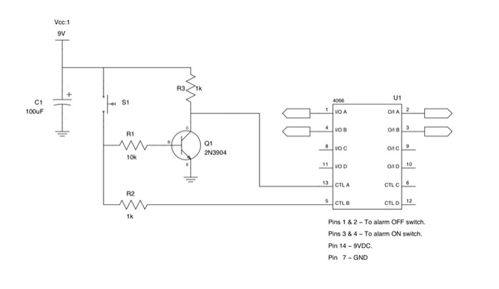
This circuit allows just under 1mA (0.95mA) of current to flow through the keyboard matrix. So far my testing has shown this to be a safe level of current, but since I do not know the exact specifications of the matrix, I am unsure how much current the matrix can safely withstand. If you have any additional information on this topic, please feel free to contact me.
Parts List:
- 1x Dell SK-8135 media keyboard. I chose this keyboard because it contains a high quality, rubber dome key matrix inside.
- 1x Inexpensive alarm clock. I used a Elgin 4028 available at drugstores for around $7.
- 1x 100 uF / 25 V electrolytic capacitor
- 2x 1 k ohm 1/4 W resistors
- 1x 10 k ohm 1/4 Q resistor
- 1x 2N3904 general purpose NPN switching transistor.
- 1x Pin-compatible 4066 chip (such as the CD4066BC) capable of withstanding 10 VDC.
The trickiest part for beginners may be locating a clean DC voltage source from the alarm clock. The image below shows the original alarm clock circuit prior to any modifications.
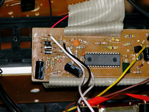
The first thing worth noting is that there are three wires that connect to the circuit board from the power supply. This is usually a dead givaway that we are dealing with an AC transformer, but there’s still a very good chance that our alarm clock will require DC voltage at some point in the circuit. Most of us should be familiar with the concept of a rectifier, or diode bridge; a circuit that converts alternating current to direct current.
A simple rectifier circuit will typically contain between 1 (half-wave) and 4 (full-wave) diodes, along with a capacitor to smooth the output. Looking at the circuit shown above, we can easily spot 3 diodes and a capacitor, all suspiciously close to the AC input. A quick look at the traces on the backside of the board confirm our suspicions. The capacitor is indeed connected across the diodes. This is a great time to break out your oscilloscope, if you have one. Here I used the fairly inexpensive USB model available from Parallax.
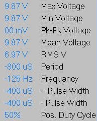
Just like that, we have located our clean ~9 VDC power source. Keep in mind that different manufacturers use different techniques, so your clock will almost certainly not look exactly like this one.
Now let’s talk about the pad that gets placed beneath the matress. I decided to use the internal keypad form a Dell SK-8135 media keyboard, because it has these wonderful little padded cups attached directly to the keypad.
We make use of the keyboard by wiring a number of the internal switches together in series. This way, the circuit is only “closed” when all of the wired buttons have been pressed, indicating that there is a distributed weight applied to the pad. Changing the number of connected buttons will allow you to adjust the sensitivity to your liking.
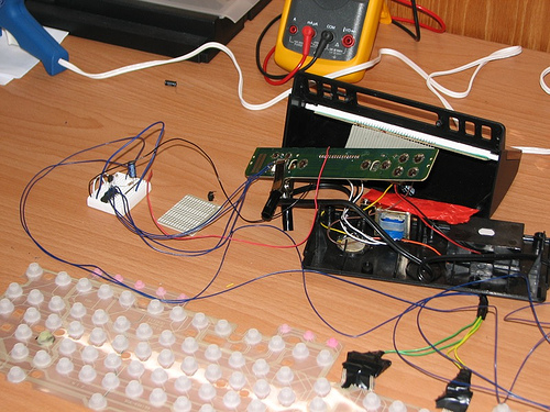
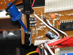
The rest of the circuit goes together quite simply, as shown in the photos and schematics above.
Interested parties can read my complete build journal to follow along with my successes, failures, and discoveries.
