William Grill
If your freezer fails you may have meat or other frozen stuffs ready to eat. Re-freezing, not generally considered an option, may be an alternative for you, but may be also a risky business. While for a short time, a freezer should maintain an acceptable temperature to keep everything from beginning to defrost, it would be nice to know if the freezer contents have been compromised and for how long. For instance…power could be lost over that weekend you spent at the lake with the power returned several hours later. This exposes the contents to the ravages of spoiling without you even realizing it.
Enter this handy gadget which is built around a small controller, an alarm and a temperature sensor. Temperature monitors are a fairly common commodity but monitors that remember and provide an audible display of how long the monitored temperature have been above a temperature set point are less common.
Referring to the schematic, Figure 1, the part count is relatively small and the total cost is ‘much less’ than a couple of those steaks you bought on sale and stashed in the freezer waiting for the right weekend. The gadget packaging is not very critical, calibration is simple and the gadget operates on 2 or 3, AA or AAA batteries.
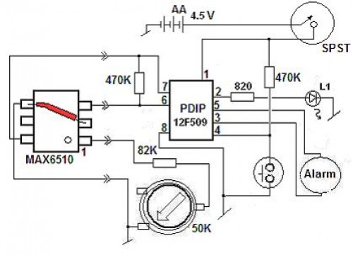
Figure 1.0
The central component is the MicroChip 12F509 controller which is programmed with everything that makes the project go. The monitoring is done periodically to conserve battery power. A monitored error is qualified and declared with a periodic chirp, described below.
The audible display is a modulated sequence of single chirps which identifies up 8 hours of consecutive ‘over the temperature trip’ measurements. The controller holds the error information even after the temperature returns to below the trip. A multi-use, momentary, switch is used calibrate, reset and to request the audible indication of the maximum time of any of up to 31 separate error events.
The alarm is a piezo-element which provides a single chirp every 15 minutes the first 2 hours, when there is more hope of saving or resolving the problem for the more likely situation that the freezer door was left not quit closed. After 2 hours the alarm chips on the hour. The controller chirps when a button closure is de-bounced and recognized. It continues to chirp out ~ every second, there after, to indicate when you have entered calibration, at 2 chirps and reset, at greater than 3 seconds. Depressing and releasing the momentary switch, following the first chirp, initiates the audible error display.
The controller was prototyped with the 8 pin dip version of Microchip’s 12F509. The temperature sensor is a Maxim MAX6510 part which provides a discrete status of resistor settable sensor trip and the detectors temperature.
The Maxim part, taken from the manufacturers data sheet, Figure 1a, used in this application, is packaged into a SOT-23 footprint, measuring about .1”x.1”. Using a small part minimizes the temperature probe’s profile.
For those less adventuresome, an 8 pin MicroChip TC624 would mount on a small perf board. There may be several resistor settable temperature trip parts that would work for this application. Typically they are used to monitor ambient air or motor temperature and may be used to enable fans in electronic hardware or provide ‘out of tolerance’ alarms.
Figure 1a
For those more adventuresome freaks, referring and following the photos, I built a small sensor mounting platform, with common perf board, with cooper pads on a single side. Two small boards are glued back to back and the sensor is glued, legs up, across the resulting edge, Figure 2.0. Be sure to mark the board which corner corresponds to pin 1, as once it’s glued down, the orientation is hidden.
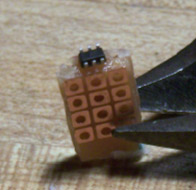
Figure 2. Sensor in rough
Shown in Figure 3, the 6 pin MAX6510 is wired per the schematic, including pin 2 to pin 4 of the sensor. Careful soldering then secures each pin of the sensor to the boards and then wires to the mechanically solid assembly. The power, ground, temp setting and discrete status leads used 28 gauge stranded wire to connect and interface to the sensor head.
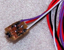
Figure 3 Sensor detail
The probe is then completed, Figure 4, with a really large straw. A slurpy straw from my corner gas station worked nicely. The sensor board is simply pushed up into straw and the wiring routed out the corner of the freezer door. The straw is taped to a ‘friendly’ out of the way freezer, upper inner wall or ceiling.
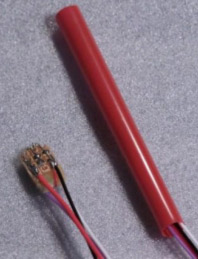
Figure 4. Finished sensor
The application really doesn’t care what the discrete status is. Temperature is monitored in this project, but any discrete sensor monitor could be substituted.
Turning our attention to the circuit card in Figure 5, it’s layout is not critical and may have a familiar format, which includes a socketed IC, trim pot and mounted piezo-element. The alarm monitor is shown to use 3 AA batteries. The controller and sensor can be operated on 2 AAA batteries or any source of ~2.6 to 5 volts. Operation issues based on voltage include the timer related accuracy, which is already ~±10% and the level of the audible alarm.
Owing to the use of the controller’s watch dog timer, WDT, the application power is minimized with the sensor un-powered and the controller asleep. The hardware is wakened every ~2.3 seconds for several micro-seconds, uS.
The assembled hardware, Figure 5 and 6, with alarm, reset button and power related parts would easily fit into a small soap holder size enclosure.
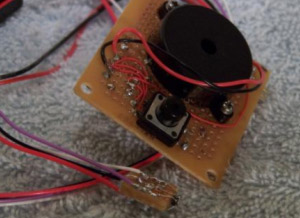
Figure 5. TOP
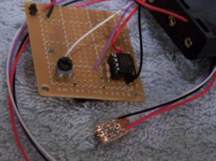
Figure 6. Bottom
Calibration is done by depressing and releasing the button switch for the ~2 seconds, (2 chirps) as described above and then setting the trim pot until it chirps continuously. In calibration mode power is asserted to the sensor and it is monitored continuously. The trim pot sets to the sensors temperature trip point. So, if in ambient 67 degrees F, so will your alarm. For the freezer application, it then best calibrated if you water proof the probe with a plastic bag, set the probe in ice water for awhile to get the probe down to 0 degrees C. Repeat the calibration instructions and then back off the trim pot until the alarm stops. This sets the sensor to ~2 degrees C below freezing, about 29 degrees F and provides an example of what rotation will corresponds to 2 degrees C, recalling that degrees in C are translated as degrees F = 9/5*C + 32
The setting can be, and should be, set lower by continuing to adjust the trim pot. When satisfied, cycle power to the board.
Taken from Maxim’s data sheet the monitor, using the 82k resistor and a 50K pot, the sensor should be settable for +15 to -26 degree C.
The coded monitor tests the temperature on power up and then approximately every 15 minutes. I have included a LED which provides an indication of activity. Due to the use of only battery power I constrained it to provide a short pulse of light on the same interval as the 15 minute temperature test cycle.
There are several parameters which can be manipulated in the code. These include, how often the temperature is tested, the audible display resolution and duration as well as small things like the button debounce time, chirp duration and spacing between audio intervals.
From comments to original article: The submitted code listing has been neglected to be included with the build instructions. This missing file can be requested by contacting the author at contact@riverheadsystems.com
