The following instructions will allow you to build a practical test tool for troubleshooting and analyzing digital and microcontroller circuits. The complete Assembly and Instruction Manual can be downloaded from the the following web Don's Projectslink:
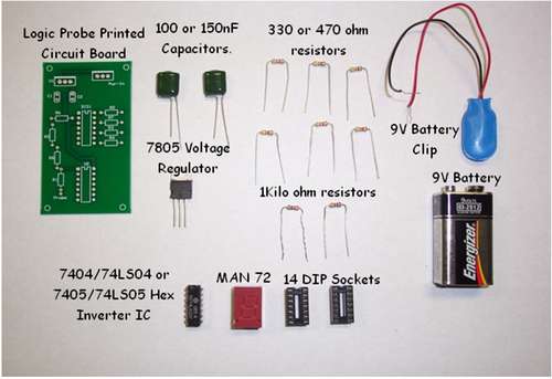
Here's the components needed to build the Logic Probe shown in the Bill of Materials (BOM) picture.
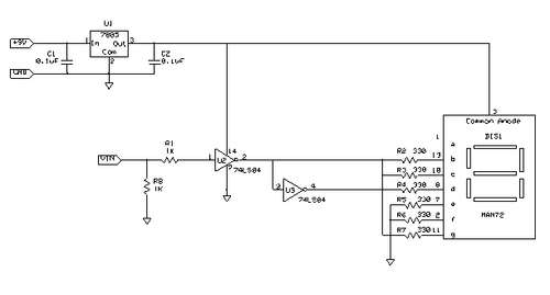
Here's the circuit schematic diagram for the Logic Probe.
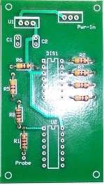
Add the 1 K and 330/470 ohm resistors onto the pcb and solder.
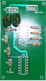
Place the (2) 150 nf (0.15 uF) capacitors onto the pcb and solder.
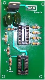
Add a 5 V Voltage Regulator IC, (2) 14 Pin DIP sockets, the Hex Inverter IC and the 7 Segment LED display components onto the pcb and solder them.
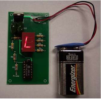
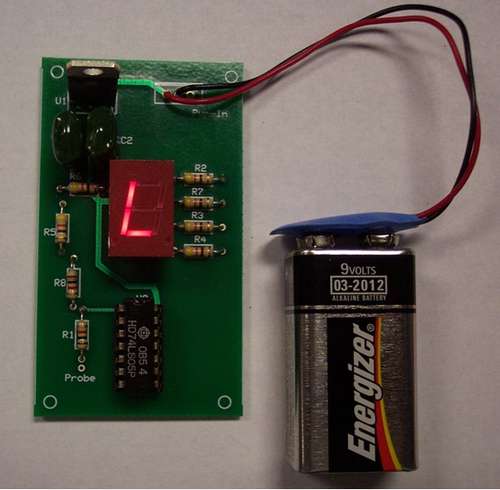
Snap a 9 V Battery to the battery clip. The Letter L should be displayed on the 7 Segment LED Display. Next soldered a red wire on the pcb where "Probe" is located. Last, soldered a black wire next to the black wire attached to the 9 V Battery Clip. Now, the Logic Probe is ready to trouble or analyze digital or microcontroller circuits.