A while back, I posted up a quick and dirty "el cheapo" method of getting started programming the Atmel AVR series chips: Ghetto Programmer (version 1.0)
Since then, I've vamped, re-vamped, and otherwise improved my setup. Thought it'd be nice to document it.
The goal was to get a flexible, compact, portable, use-anywhere, AVR-based microcontroller prototyping environment. On the cheap(ish).
So without further ado, here's the Ghetto Development Environment (GDE) (version 1.2).
The basic kit contains the following stuffs:
USB programmer. Because you want to be able to program microcontrollers from your laptop anywhere. And because USB is a very handy source of +5v.
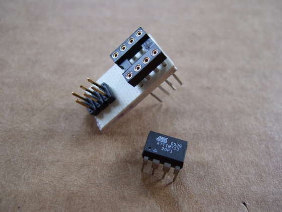
Programming cradles. One for each kind of chip you're playing with. For me, that means one with 8 pins (ATtiny13, 15), one with 20 pins (ATtiny 2313), and one with 28 pins (ATmega8).
Blinkenlights. When something's wrong with your code, nothing clears it up like sticking lights in to diagnose. Plus, the LED blinker program is the "Hello World" of microcontrollers.
Breadboard. It's a development kit, after all.
In Ghetto Programmer (v.1.0) I used a parallel port programmer. It's great because it's simple and cheap and fast. But my laptop doesn't have a parallel port.
I played around with making serial port programmers for a bit, but honestly they're just as complicated as the USB version and even serial ports are becoming scarce.
Indeed, my laptop's only really got USB. So USB it is. Looking around, the USBTiny programmer is pretty simple and works with the free GNU/AVR-GCC tools.
Do it yourself or buy a kit?
The DIY way is good if you can already program an ATTiny2313 (with parallel programmer) and have a 12MHz crystal sitting around. USBTiny Page lays out the basics.
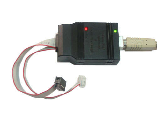
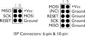
He terminates the programming cable with a parallel port, but I'd finish it up in a standard 6-pin header if I were starting afresh. (Why? Because it's standard.) Here are his pin-outs, and check the image below for the cable layout.
PD3 - MISO
PD5 - Reset
PD6 - SCK
PD7 - MOSI
If you make your own, please learn from my experience and put it into a nice plastic box. If you don't, it'll fail eventually when the 12MHz crystal breaks off. Which is why I now use...
The quick-and-elegant way is Ladyada's USBtinyISP kit. It'll set you back $22, but you get a nice PCB, pre-programmed ATTiny2313, and a clean box with nice cables. Raw parts are like $15-16 anyway, and you don't have to call up Digikey and then worry about programming up your own 2313. Takes 30 min - 1 hr to solder it all together.
Splurge. Trust me.
(No affiliation, satisfied customer)
And just saw this link: Ladyada's AVR Tutorial which seems pretty good to me.
(And do note that Ladyada's design and the original USBTiny use different USB product identifier codes -- you'll have to find the ID strings and re-compile avrGCC if you're switching between the two. I think there's instructions on the respective webpages.)
In case you're on a Ubuntu Linux system and using the USBTiny programmer, here's the commands that'll get the whole toolchain up and running:
sudo apt-get install build-essentials avr-libc binutils-avr gcc-avr avrdude
(tested on Hardy Heron)
If you have an AMD64 arch, you may also need: byacc libusb-dev flex bison libc6-dev
and then to compile AVRdude by hand:
(
wget
tar xvzf avrdude-5.5.tar.gz
cd avrdude-5.5
## Patch needed for AMD64:
wget
patch -p1 < avrdude-5.5.usbtiny.64bit.patch
./configure
make && make install
sudo avrdude -p attiny2313 -c usbtiny ## to test
)
If you see something like "avrdude: AVR device initialized and ready to accept instructions" then you're done.
Oh yeah, and credit to Wendel Oskay for the diagram of the standard programmer pinouts.
In Ghetto Programmer v.1.0 I used a programming cradle with a non-standard pin input and with female pin-headers to stick stuff into.
Non-standard pins are a bad idea because you'll not be able to use your cradle with someone else's programmer, and vice-versa.
Female pin-headers were fun because you could directly plug LEDs into them, but when I'd start doing something more complex, I'd end up wiring it into a breadboard anyway. With the new cradle, I cut out the middleman. Less hand-wiring = better.
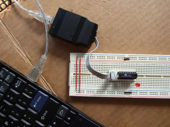
But the biggest advantage of this cradle design is that you can plug in the cradle almost anywhere you could plug in the AVR chip. This turns out to be huge. Instead of designing ISP circuits into your robot or whatever, you just stick this cradle thing into the IC socket. Then you can program/re-program your robot's brain in circuit. When you're done developing, plug the AVR in directly and you're on to the next one.
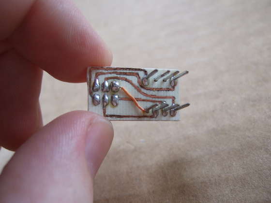
Making the cradles is easy enough -- all you need to do is connect the pins from the 6-pin header to the right places on the chips. This time 'round, I used etched PCBs. You can just as well hand-wire the whole thing on perfboard.
The ATTiny13/15 cradle is made with an 8-pin wire-wrap socket. I love these. It's easy to insert the chip into its nice round holes and the long legs provide extra clearance on the breadboard. I made the PCB traces by freehand with a Sharpie.
The ATTiny2313 cradle was made with Eagle and the laser paper toner transfer method. I couldn't find any 20-pin wire-wrap sockets, so I had to resort to a 20-pin regular socket soldered onto 2 10-pin pin headers. This ends up with a cradle with shorter legs, but it works. The schematic and the PDF I used for the circuit are below.
On both, I had to hand-wire an extra line. Such is life.
2313_cradle_hobby_ground_plane.pdf 5 KB
2313_cradle.sch 8 KB
Simplicity itself. I wouldn't mention these at all if they weren't so damn handy.
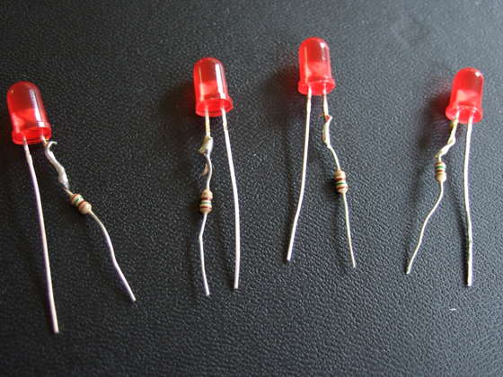
Solder a resistor (150-220 ohms is a good value.) straight onto the negative lead of some LEDs. It'll light up from around 2v-6v without burning out.
And the resistor helps you to remember which side is negative.
Stick them wherever you want to know there's electricity. Figure out if that transistor is blown. Turn a nicad battery pack into a long-lived nightlight.
Use a blinky-code interface to read values out of your microprocessor (slowly). Or make 8 of them and you've got a one-byte display (plus the active ingredient in Cylon eyes.)
Make them. Make many. Make them now.
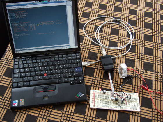
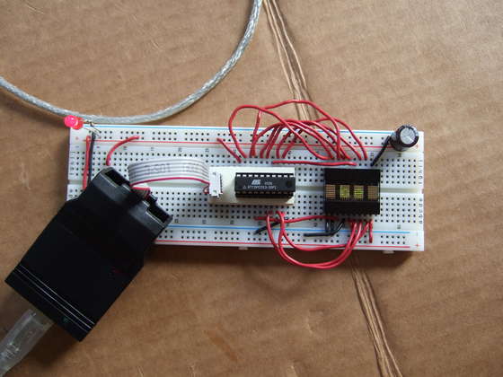
So this "system" meets almost all my development needs. It's modular, scalable, compact, and portable.
For instance, I worked out the routines for running scrolling messages on the 4-digit display (intro page) on the plane on the way to a friend's wedding. Makes a good icebreaker with the flight attendants.
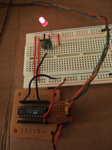
This potientiometer -> ADC -> PWM-driven ammeter setup was breadboarded, coded, and debugged entirely between my couch and dining table, and cleans up in like 2 min when friends come over. (It's the alarm-time-setting part of what's going to be a meter-clock.)
I bring the setup to work sometimes when I feel like playing hooky.
Add a small bag of goodies (some capacitors and resistors, hook-up wire, transistors, piezo speaker, photodiodes, microphones, small motors, etc) and you'll be so far ahead of MacGuyver it's not even funny.