Four-LED left and right sequence
Particularly suited to motorcycles
Circuit diagram:
Parts:
|
R1 |
500K 1/2W Trimmer Cermet or Carbon |
|
R2 |
47K 1/4W Resistor |
|
R3,R4 |
1K 1/4W Resistors |
|
R5,R6,R7,R8 |
10K 1/4W Resistors |
|
C1 |
1µF 63V Polyester or electrolytic capacitor |
|
C2 |
220µF 25V Electrolytic capacitor |
|
D1-D8 |
LEDs Yellow ultra-bright types |
|
Q1,Q2,Q3,Q4 |
BC337 45V 800mA NPN Transistors |
|
IC1 |
7555 or TS555CN or TLC555CP CMos Timer IC |
|
IC2 |
4017 Decade counter with 10 decoded outputs IC |
|
SW1 |
Vehicle Turn Lights switch (See Comments) |
|
Battery |
12V Vehicle battery |
Comments:
This device was designed on request and allows sequential operation of four Leds either to left or right direction, obtained by means of a 7555 CMos timer IC (IC1) wired as an astable multivibrator driving a Decade counter (IC2). This IC is set to count a sequence of four by connection of pin #10 to pin #15, but any sequence count in the 2-10 range can be set by choosing the appropriate pin connection. Obviously, LEDs, Transistors and their respective Base-limiting resistors must also be added or omitted accordingly.
R1 is a variable resistor (Trimmer), used to set the desired speed of the LEDs. SW1 is a change-over switch that should already exist in your motorcycle, having a center-off position and Turn-left and Turn-right positions.
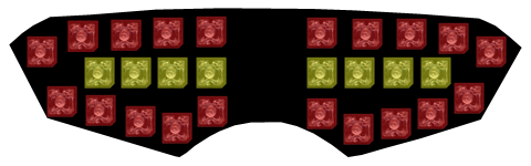
D1, D3, D5 and D7 are the Turn-left LEDs; D2, D4, D6 and D8 are the Turn-right LEDs.
For a motorcycle they are arranged on a single board about 20 - 25 cm wide as shown in the image below. The outer red LEDs are the tail/brake lights and can be driven by a circuit like the LED driven tail/brake Light Cluster available on this website.
Note:
- The use of high brightness, high efficiency yellow LED types of suitable size is mandatory.
