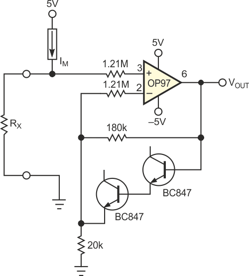
The circuit in Figure 1, using a low-offset amplifier, is a basic ohmmeter circuit common in multimeters, except for the addition of the two diode-connected transistors. A current source supplies a selectable current, IM, to ranging from 100 nA to 1 mA to RX. An A/D converter with a 400-mV reference voltage reads the voltage drop across RX. Manufacturers of handheld DMMs limit IM to 1 mA to save battery power. So, to measure resistance lower than 40 Ω with 10-mΩ resolution, you need to amplify the voltage drop across RX by 10 times to fully use the ADC's dynamic range.
 |
||
| Figure 1. | The addition of two diodes in the feedback loop prevents excessive input current in the OP97. |
|
For high-precision measurements, you need a low-offset, high-input-impedance amplifier. The moderate-power OP97 from Analog Devices is a good choice. Because the OP97's inputs have back-to-back diode protection, differential input voltages greater than 1 V cause current to flow through the diodes, causing measurement errors. For example, errors can occur when you try to measure a high value of RX, say a few megohms, with a wrong value of IM. Not all the measurement current goes to RX, so the converted value is inaccurate.
 |
||
| Figure 2. | Without the diodes in Figure 1, the amplifier saturates, and current flows in the differential inputs. | |
Figure 2 shows VOUT and the current that goes into the noninverting input of the OP97 (without the diode-connected transistors), configured for a gain of 10, for input voltages as high as 2 V. For VIN greater than 1 V, the leakage current becomes non-negligible in comparison with the lowest values of IM. A simple way to limit the leakage current is to limit the gain of the amplifier for high input voltages.
 |
||
| Figure 3. | The diodes in Figure 1 prevent the amplifier from saturating, so the input current remains negligible with respect to IM. |
|
To prevent the differential input voltage from exceeding 1 V, you can reduce the gain by limiting the voltage across the feedback resistor. When that voltage reaches approximately 0.8 V, for example for IM·RX ≈ 10 mV, the two diode-connected transistors start to conduct and limit the gain. Transistors are better than signal diodes because they have lower leakage current at low voltages. Low leakage current is critical in avoiding additional errors when reading the output of the OP97. Figure 3 shows VOUT and the current that enters the noninverting input of the OP97 for input voltages as high as 2 V in the circuit of Figure 1. The leakage remains low in comparison with IM.