Overview
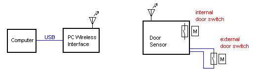
The “Simple Wireless Security System” monitors the open/closed state of two (garage) doors. Sensors detect the state of the doors, and a Zigbee wireless transceiver sends the state information to a PC. The PC runs a GUI application that shows the state of the doors.
Specifications
- Physical devices consist of a door sensor and a (WindowsXP) PC.
- Visually indicates, within 10 seconds of the physical event, the open/closed state of a (garage) door.
- Audibly indicates an alarm condition. The sound is approximately one second in duration, sounded three times, separated by one second of silence. After the third sound there is ten seconds of silence.
- Detect the following alarm conditions:
- Door is open and time is between 10:00pm and 6:00am.
- No message received from door sensor for over two minutes.
- More than three unknown messages received at communications port – this alarm condition never reverts back to a non-alarm condition.
- An alarm is indicated within 1 minute after the condition occurs.
- The following events are logged to an ASCII readable file,
- Door becomes open.
- Door becomes closed.
- Alarm condition “1” becomes active.
- Alarm condition “1” becomes inactive.
- Alarm condition “2” becomes active.
- Alarm condition “2” becomes inactive.
- Alarm condition “3” becomes active.
- Communications between door sensor and PC is wireless.
- Door sensor is battery powered.
- Door sensor runs for at least one year between battery changes.
- Door sensor monitors two doors.
- Door sensor physical environment: -30F to 120F, 5-90% RH.
- PC application shows the door open/closed state (both doors) and textually shows alarm conditions. An icon exists in system tray and it changes depending on the state of the system.
- Both the audible and visual alarms can be silences for 60 minutes.
- System Design Details
Block Diagram
Door Sensor Outgoing Messages
Bits 7-4: 0001 (sensor address – up to 16 sensors can exist in the system)
Bits 3-2: 00 unused in this application
Bit 1: internal door switch, 1 if door is open, 0 if door is closed
Bit 0: external door switch, 1 if door is open, 0 if door is closed
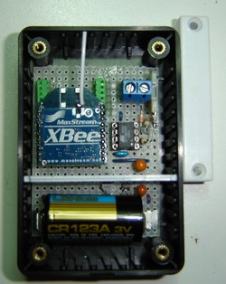
Door Sensor Hardware Design Details
The door sensor consists of the following main hardware pieces,
- Atmel ATtiny45 microcontroller
- Maxstream XBee Zigbee transceiver
- Reed switches and magnets
- 3.0V Lithium battery
- 3.0V step-up switching regulator
The ATtiny45 monitors the open/closed condition of two reed switches. The open/closed states are formatted into a message and sent out the ATtiny45’s UART interface to the XBee. The XBee wirelessly sends the message to another XBee node.
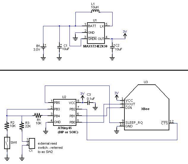
Circuit Summary
- Door open/closed state is determined using reed switches in a resistor divider circuit.
- The XBee wirelessly sends data to compatible nodes.
- Interface between ATtiny45 and XBee is TTL level (3.0V) UART including Tx and Rx. CTS-RTS handshaking is not used since system protocol is very simple (single byte).
- The ATtiny45’s firmware controls the power state of the XBee at the SLEEP_RQ pin.
- 3.0V battery + step-up regulator supplies power to the circuit.
Processor Selection
- Physical Size: to keep the door sensor size as small as possible, the ATtiny45 has a small package size. The prototype uses 8-pin DIP; however, a production version would use the 8×5mm SO-8 package or the 4×4mm MLF package (requires change in schematic).
- IO Pins Needed: (1) UART-Tx, (1) UART-Rx (not requires since door sensor does not receive any messages), (1) UART-CTS, (1) Power down control (1) reed switch power, (1) reed switch read = 6 total. The ATtiny45 has 6 available IO.
- Program Memory: The ATtiny45 has 4K bytes of program memory. A first level code prototype was used to show that this is sufficient. Under 80% use is desired.
- Data Memory: The ATtiny45 has 256 bytes of RAM. The firmware does not require large portions of RAM, other then the stack.
- Power Supply: The ATTiny45 can run at the 3.0V available from the circuit’s voltage regulator. According to Figure 24-2 of the ATtiny45’s data sheet, the ATtiny45V-10PI can run up to a 10MHz CPU frequency at 3.0V. This is sufficient for the desired CPU frequency of 8MHz.
- Power Consumption: The ATtiny45 includes low power modes. The “idle” sleep mode will be used. During sleep, the CPU clock is running at 31kHz (reduced just before entering sleep mode), so according to Figure 25-6 of the ATtiny45 data sheet, current draw is about 0.6mA.
- Internal Oscillator: To keep the size of the door sensor as small as possible, it is desirable that the microcontroller have an internal oscillator – the ATtiny45 has such a feature.
- CPU Speed: The microcontroller must be able to drive the UART interface at 9600 baud. The ATtiny45’s internal oscillator running at 8MHz meets this requirement.
- Interface: The ATtiny45 supports the required UART interface through its USI feature. It is a half-duplex implementation – which is acceptable for this application.
Wireless Transceiver Selection
- XBee uses Zigbee 802.15.4 and custom transport layer created by Maxstream. Supports multiple nodes in network.
- XBee was lowest cost, readily available at time of design start.
- Simple UART interface, minimally Tx & Rx.
- Power down mode (hardware pin activated), 10uA
- FCC precertified (note that this does not remove the requirement of standard FCC testing (non-intentional radiator) on the finished device).
- XBee is ready-to-run, no RF expertise/equipment is needed.
|
Ref. Designator |
Value/Part No. |
Description |
|
U1 |
3.0V step-up voltage regulator |
|
|
U2 |
Atmel ATtiny45V-10PI |
Microcontroller |
|
U3 |
Maxstream XBee |
Zigbee wireless transceiver |
|
R1, R2 |
10K, 5%, 1/8W(min) |
Resistor (general) |
|
R3 |
22K, 5%, 1/8W(min) |
Resistor (general) |
|
C1, C2 |
10uF, 6V(min) |
Capacitor, tantalum |
|
C3 |
0.1uF, 6V(min) |
Capacitor, monolithic ceramic |
|
B1 |
Panasonic CR123A |
3.0V Lithium, 2/3A package |
|
L1 |
Coilcraft DO1608C-103MLB |
Power inductor |
|
C1 |
2 position screw terminal |
|
|
SW1, SW2 (external) |
Reed switch, N.O. |
Development Setup
- WinAVR 20060421 – C compiler
- AVRStudio 4 (4.12, service pack 2, build 472) – IDE, editor, programming interface to STK500; open gdm.aps
- Fuse Programming: CKDIV unchecked, Internal 8MHz 0ms checked, Disable Reset on PB5 (don’t do this one until all code is well checked out since ISP programming is no longer possible), no brownout detection, no watchdog. Note: after programming these fuses, it was necessary to reduce the ISP frequency to 4kHz.
- XBee is configured using Maxstream’s X-CTU software application (temporarily inserted into the PC Wireless Adapter). The only change from standard setup is to set sleep mode for “Pin Hibernate”.
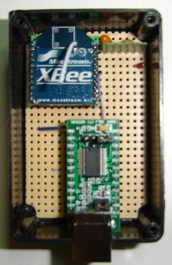
PC Wireless Adapter Hardware Design Details
The PC Wireless Adapter consists of the following hardware pieces,
- Maxstream XBee Zigbee transceiver
- DLP Designs UM232R
- 3.0V LDO voltage regulator
The XBee device receives messages from the door sensor and sends the messages out its UART port to the UM232R. The UM232R transfers the messages to the PC using USB.
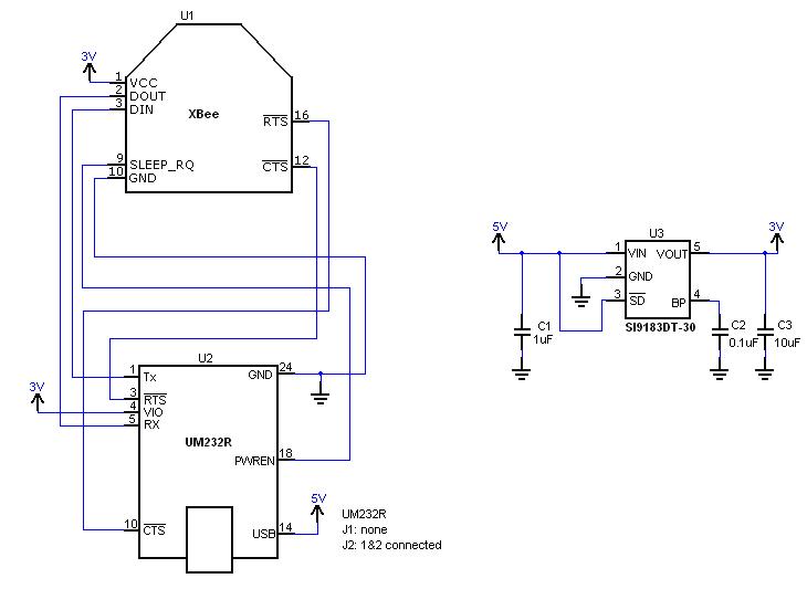
Power
- Entire circuit is powered by USB power (therefore circuit must not consume more than 500uA during USB suspend, 100mA at startup, 500mA during normal operation).
- In order to meet USB shutdown requirements, the UM232R supports a power down control that controls the SLEEP_REQ pin of the XBee.
- The 3.0V LDO provides power to the XBee. Source power is from USB power. The UM232R does provide 3.3V@50mA; however, the XBee can draw up to 95mA during transmit and receive operation, so the UM232R’s 3.3V power supply cannot be used.
- 3.0V LDO was chosen instead of 3.3V LDO since XBee consumes less power at 3.0V (although power is not of great concern in this application).
|
Ref. Designator |
Value/Part No. |
Description |
|
U1 |
Maxstream XBee |
Zigbee wireless transceiver |
|
U2 |
DLP Designs UM232R |
USB-to-UART, 24-pin DIP |
|
U3 |
3.0V LDO voltage regulator |
|
|
C1 |
1uF, 16V(min) |
Capacitor, ceramic |
|
C2 |
0.1uF, 16V(min) |
Capacitor, ceramic |
|
C3 |
10uF, 16V(min) |
Capacitor, ceramic |
The Main Window
When the PC Application is started, the main window is displayed,
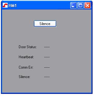
- The “Silence” button is used to stop visual and audible indicators. When pressed, it starts a 60-minute countdown that is shown in the “Silence:” text near the bottom of the window.
- The “Door Status:” text shows “closed”, “open”, or “open, ALARM” depending on the state of the doors and door alarm condition.
- The “Heartbeat:” text shows “OK” while messages are being received periodically from the door sensor (at least one in last two minutes). “No heartbeat” is shown otherwise.
- The “Comm Err:” text shows errors with the communications link, such as unknown messages received.
Log Entry Format
Format: mm/dd/yyyy
Messages:
|
Message Text |
Explanation |
|
CC |
Both doors closed |
|
CO |
Door 1 (SW1) closed, door 2 (SW2) open |
|
OC |
Door 1 (SW1) open, door 2 (SW2) closed |
|
OO |
Both doors open |
|
+Door Alarm (open, alarm) |
Door alarm has become active |
|
-Door Alarm (open) |
Door alarm has become inactive |
|
-Door Alarm (closed) |
Door alarm has become inactive |
|
+Heartbeat Alarm |
Heartbeat alarm has become active |
|
-Heartbeat Alarm |
Heartbeat alarm has become inactive |
|
Comm Err (bad msg:x) |
Bad message received, where x is the message (one byte) |
Source code and .hex-file for microcontroller, source code and .exe-file of PC Application - download
