What do you do with an old phone, a microcontroller and lots of time?
You hook the old phone's LCD screen to the computer USB of course!
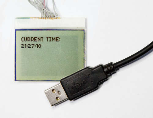
In this project we're going to communicate with a Nokia 3310 LCD display over USB! How are we going to do that? We're going to connect the LCD display to an Atmel ATmega8 micocontroller and talk to it using the SPI, then connect the ATmega to a PC using V-USB.
The Nokia 3310 LCD display is easy to find, and has a very well documented interface, so it's perfect for hobby use! Not only that, but we're going to use V-USB (Formerly AVR-USB) as our USB driver on the AVR chip. This makes the project very easy to pull off the ground.
V-USB is very slow, so you cannot do any fancy animations this way, but is perfect for updating the display with text! Also, when using USB, you can use this on pretty much any computer. It does require libusb though, but libusb is cross platfrom, so that shouldn't be a problem. Or, if you're really hardcore, you can write your own driver for this project (This is way out of the scope of this instructable)!
What uses does thing have?
As I mentioned, V-USB is pretty slow, so it's best for sending text. Even through this is a little drawback, there is still a lot of stuff you can do with it!
Display RSS feed, Twitter updates, weather, temperature, free disk space, unread e-mails. You are not limited to just display text though. If you're feeling really fancy, you can make a 1-bit picture slideshow! Only your imagination (And the slow speed of V-USB) limits you :)
What features does the code have?
- Built-in font and support for writing ASCII characters
- Character wrapping (Prevents characters from being printed over 2 lines if end of display is reached)
- USB connected and powered
- Easy to expand
The code is open source (Both firmware and host software), so you're free to do whatever you want with it. (This only includes the software I have written. See the license for V-USB for further use of that, same goes for libusb. Both licenses are included in the source files.)
For this project, you need some components, this include:
- IC1 - Atmel ATMega8
- LCD1 - PCD8544 (Nokia 3310 LCD display)
- ZD1, ZD2 - 3,6v Zender dioes
- C1 - 10uF capacitor
- C2, C3 - 20pF capacitor
- R1 - 1,5K ohm resistor
- R2, R3 - 68ohm resistor
- Q1 - 12MHz crystal
You also need an USB cable, your standard soldering tools and thin wires. (As thin as possible. I used IDE cable wires, works pretty well. )
Schematic diagram

I did not have 3,6v zener diodes or 68ohm resistors available, but I had 3,2v zener diodes and 33 ohm resistors, so I used those instead. However, I highly recommend using the listed components! If you gamble like I did, the device might not be correctly recognized and might show up as "Unknown Device".
If you have trouble finding parts, may I suggest old broken electronic devices? Not only can you find most parts you need in old electronic devices, but you're also being "green" by recycling! All the parts I have used in this project comes from recycled components (Except for the ATMega8).
When you're soldering, be sure to note the D+ (Green ) and D- (White ) on the USB cable. It's very important not to mix those!
Here's the pinouts for various USB connectors.
Also, if you do I like I did and solder the wires directly onto the LCD display, be very careful to not make any bridges between the connections! The connections are very small, and trust me, it's not fun when you realize the only problem with your circuit is a bridged connection on the display.
Download the source code or hex files, compile and upload to your chip.
Once you've uploaded the firmware to the microcontroller, detach the programming cable. If you've done everything correctly , the display should now say "Display Initialized" and your computer should notify you that an USB device has been plugged in.
If you have trouble burning the chip:
- Is the AVR powered? You can use power from the USB port.
- Check for any bridges in your soldering.
- See if you have mixed the MISO and MOSI wires. It's pretty quick to mix those.
- Is the crystal correctly soldered?
If the display does not work:
- Is the screen powered (It powers directly from the USB, just like the AVR)
- Make sure you have not flipped the pinout on the display. It's pretty quick to get it backwards.
- Have you mixed any of the SPI wires?
- Make sure the VOUT on the display is connected to a grounded capacitor.
- Make sure the RESET on the display is properly connected and to the correct pin on the AVR.
If your computer does not find the device over USB:
- Have you mixed the D+ and D- wires?
- Are the zener diodes correctly soldered?
- Does the D+ and D- signal go to the correct pin on the AVR?
In the following part of article we will consider high lights in the microcontroller and Host-device software. We will stop on the most important functions participating in realisation of the USB interface.