Do you need to add a distance sensor to your embedded project ? Build this simple ultrasonic range finder !
This quick & dirty PIC ultrasonic range finder will find a place in numerous projects : presence detector, robotics, car parking, distance measurement...
With a few cheap components and less than 200 bytes of code, this sensor will work from 30 to 200 cm, around 1 cm accuracy, with underflow and overflow indication.
How does it work & Circuit schematic
Everybody knows the speed of the sound in the dry air is around 340 m/s. Send a short ultrasonic pulse at 40 Khz in the air, and try to listen to the echo. Of course you won't hear anything, but with an ultrasonic sensor the back pulse can be detected. If you know the time of the forth & back travel of the ultrasonic wave, you know the distance, divide the distance by two and you know the range from the ultrasonic sensor to the first obstacle in front of it.
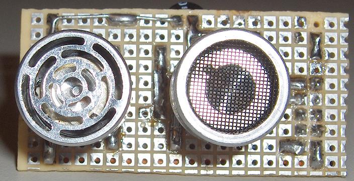
Here we use an ultrasonic piezzo transmitter with its receiver, they are very efficient, easy to find and quite cheap.
First, we have to send the pulse : it is easy to get a 40 Khz pulse from a PIC16F877A PWM output. You can drive an ultrasonic transmitter directly from the PIC output, but the sense range will not exceed 50 cm. Using a transistor and a resonator circuit, the ultrasonic transmitter will get around 20 volts and the sense range will be extended up to 200 cm.
Second we have to sense the echo : the piezzo receiver can provide a few dozens of millivolt, this will be enough for a PIC ADC with 4 mV resolution without extra hardware.
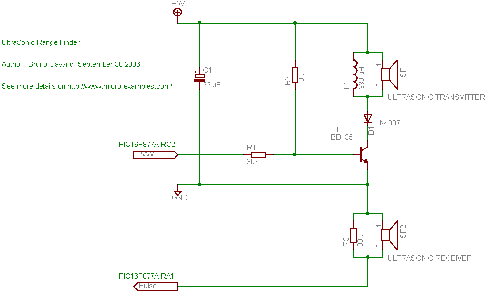
C1 is a decoupling capacitor. The PWM pulse from the RC2 pin of the PIC drives the T1 transistor base through R1 resistor. A 330 µH inductor is added in parallel to the piezzo ultrasonic transceiver, to form a LC resonnator, the D1 diode protects T1 from reverse voltage. The ultrasonic receiver is directly connected to the RA1 pin of the PIC (ADC channel number 1), with R3 in parallel as impedance adaptator.
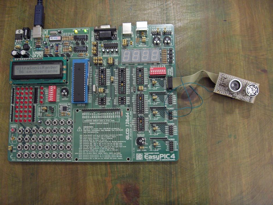
The prototype board
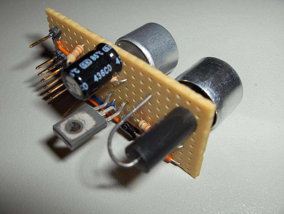
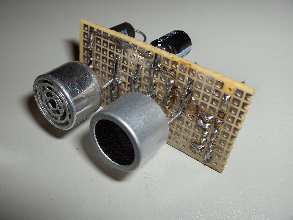
Take care to align as best as possibe the transmitter with the receiver .
I tested it with an EasyPic4 development board from mikroElektronika:
Of course, this ranger is very basic and have a few drawbacks :
- A little shock to the piezzo receiver cell could lead to a wrong measurement,
- Since ultrasonic pulse is not coded, any other ultrasonic source will put the mess :
So, Unwanted underflow or overflow conditions may happen. This is the price of the very simple design of the ranger.
This is what you should see on your scope, if you probe to the ultrasonic receiver pins :
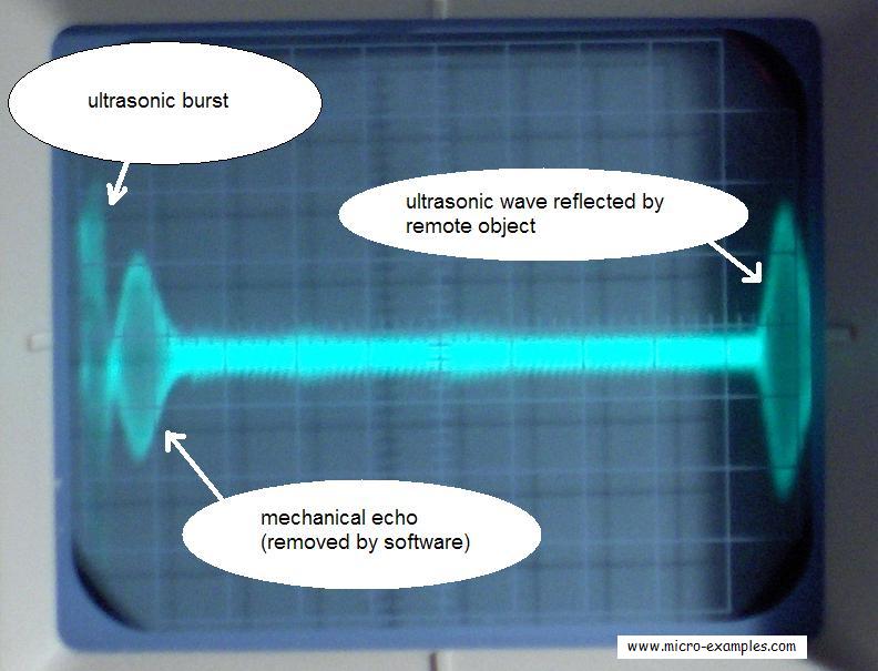
Horizontal : 1 ms/div
Vertical : 5 mV/div
The mechanical echo is removed by a software delay.
The reflected wave is around 40 mV peak to peak, it comes around 9.5 ms after the ultrasonic burst, if we say that sound velocity is 340 m/s it means that the object distance was around 0.0095 / 2 × 340 = 1.615 meters.
Actually, it was the ceiling, it was 172 cm above the circuit, the LCD wrote 170 cm.
I hope this basic project will make a good start for yours !
Downloads