Introduction
This device allows solar cell arrays to be connected to either conventional lead-acid, sealed lead-acid, or lithium storage batteries without fear of overcharging. It allows two different electrical loads to be driven from the batteries at two different charge states to maximise power usage efficiency.
This project came about after I purchased a Camping Gaz thermoelectric portable refrigerator for keeping drinks cool while out camping. The existing power control circuit in this fridge aims to avoid discharging a car battery by ensuring that it only runs down to a certain voltage. This means that it will only run for a short time after the engine is turned off. While a sensible precaution, this prevents efficient use of solar power to drive it. The existing circuit also suffers from oscillation caused by voltage drops in the wiring from the unit to the power source, generally a cigarette lighter socket; Rather than switching off cleanly the load relay spends several tens of minutes clicking on and off uselessly as the car battery voltage slowly drops back from its on-charge voltage.
I wanted to be able to get some level of refrigeration for a few minutes even if the weather was not especially sunny. What I needed was a storage battery of a few amp-hours, a solar panel for charging, and a controller circuit to turn on the fridge when enough charge had built up for a few minutes operation. The original relay based power control circuit in the fridge was removed and the power input wired direct to the fan and Peltier effect cooling unit. The nominal current draw of the fridge is 4A.
Batteries
There is space inside the regulator enclosure for about 7Amp-Hours worth of surplus mobile phone lithium batteries. Three 3.6V nominal voltage cells are wired in series which produces a battery of 10.8V, then multiple banks of three are wired in parallel. The voltage varies over the charge cycle from 3 X 3.0 = 9.0V when fully discharged to 3 X 4.1 = 12.3 V which is the maximum allowable on-charge voltage. Higher voltages will destroy these cells. The 12.3V maximum charge voltage allows the battery to be charged from 12V solar panels and the 9.0V full discharge voltage allows most non-critical 12V equipment to run the batteries right down to empty without over-discharging them.
An external battery can be connected if needed but if it is a different technology the internal one must be disconnected first. The external battery may be lithium as described, conventional lead acid, or sealed lead acid and the appropriate voltages are selected on an internal DIP switch.
The circuit is designed to draw very little current so that some charge can be accumulated even when the weather is quite dull.
Circuit Operation
In the actual device the transistors are bolted to the aluminium case. The schematic diagram shown here represents how the circuit would be built if all components were on-board. Separate paths for load current and voltage sensing allow the battery voltage to be measured accurately even under loads of several amps.
The LM4041 provides an accurate low-power voltage reference for the sensing circuit. This 1.225V reference is used directly for the conventional lead-acid setting and via two alternative dividers for the sealed lead acid and lithium voltages. Using a 1% version for the voltage reference and 1% resistors in these dividers keeps us from going too far above the magic 4.1V limit on standard lithium cells without having a pesky trimmer, or worse, a set of trimmers. As the voltage across the battery rises under charge, the main load output will be switched on when a voltage some way above the fully discharged level is reached. If the load current exceeds the available solar charge current, the batteries will drain back down to the fully discharged state and the load will be disconnected again. Some hysteresis avoids the load switching on and off too frequently, but this all depends on the available charge current, battery capacity and load current. If the charge current exceeds the load, the battery voltage will continue rising until the full charge voltage is reached. At this point the secondary load is turned on to prevent overcharging. If no secondary load is naturally available, one must be provided in the form of a resistor. If the standard load current exceeds the maximum output of the solar array this is not needed. IRF350LC MOSFETS are used for load switching which allows loads of more than 10 amps to be switched. A dual CMOS rail-to-rail output op-amp is used which simplifies the calculation of the switching voltages. LED indicators drawing about 2mA each show which loads are turned on.
If lead acid batteries are used then its worth noting that there is no temperature compensation on the charge voltages, so it's best to keep them between 10 and 30 degreesC or the -2mV/K coefficient of this technology might result in overcharging of sealed gel units.
Switching Voltages
| Batteries | Main Load V rising |
Main Load |
Second Load V rising |
Second Load V falling |
| Conventional Lead-Acid | 11.06 | 10.37 | 14.16 | 13.66 |
| Sealed Lead-Acid | 10.77 | 10.10 | 13.79 | 13.3 |
| Lithium | 9.606 | 9.006 | 12.3 | 11.86 |
Use In The Field
Applying a load only to the secondary output, you can choose to charge up the batteries to near maximum and dump excess power into the load only to stop overcharging. Applying the load to the main load output extracts as much power from the system immediately as it is generated. For camping fridge operation one might typically connect to the main load output most of the time, possibly switching to the secondary output if power was needed for some other purpose on the main load e.g. charging a mobile phone battery, or if it was desired to store up charge for a period of prolonged fridge operation.
 |
|
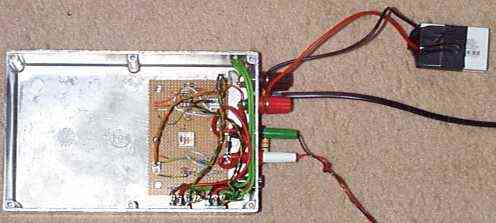
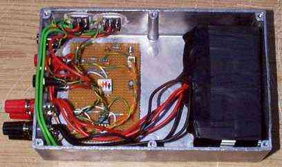
Picture of the insides while under test - the battery connected here is just one group of three lithium cells. |
 |
|
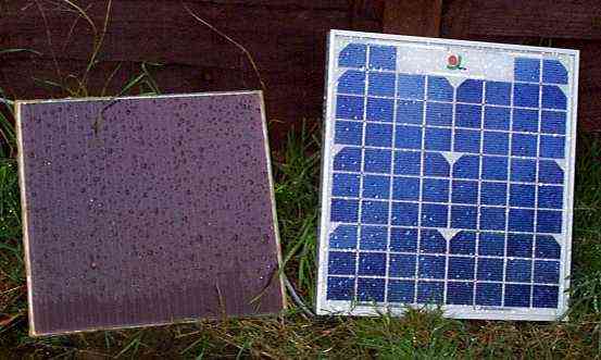
Picture of two panels out in the garden under the solar intensity levels typically found in the UK. |
The panel on the left is a cheaper amorphous silicon panel bought from Bull electrical. They have a higher leakage current and must have a Schottky diode in series with them to avoid the battery discharging through the panel in dark conditions. They are cheap but you have to spend time sealing the edges against moisture with epoxy, so its not really worth the hassle. The weatherproof crystalline silicon panel on the right is also from Bull electrical and is rated at 12V 10 Watts under full sunlight. The panels here are connected in parallel after the Schottky diode to provide test power for the regulator circuit.
The cheapest mainstream source of crystalline panels in the UK at the moment seems to be Maplin who do a 12V 15Watt panel for £99. This will give you 1.25Amps in full sunlight so you can see that even then, a 4A fridge is never going to run constantly.
However, the advantage of using solar power for outdoor refrigeration is that the power is most available when it is most needed.
 |
|
|
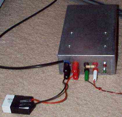
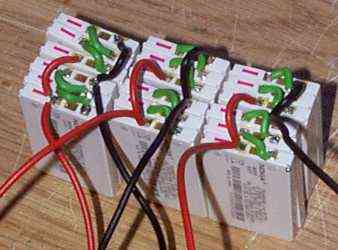
A nominally 10.8V 5Ah lithium battery exposed, and then wrapped up in the box. |
|
Note the use of good thick battery wiring to avoid losses when on-load. Mobile phone lithium batteries are designed to supply up to 2A current pulses in GSM phones. I may need to parallel up another two series batteries of 3Xcells and squeeze them into the box in order to avoid the protection circuits internal to the cells tripping when driving the fridge.
