Keypads are a very commonly used input device in microcontroller-based systems. In a keypad, multiple switches are arranged in rows and columns so that they could be interfaced to a microcontroller with a minimum number of I/O pins. For example, a 12-key keypad is arranged in a 4×3 format, which allows to interface the 12 keys to a microcontroller with only 7 connections. The location of each key on the keypad is defined by two coordinates: the row and the column. When a key is pressed, it connects its row with its column. The microcontroller must scan all the rows and columns to find out which key has been pressed. This is the most common way of interfacing a keypad to a microcontroller. There are tons of resources on the internet regarding this technique and so I am not going to discuss it here.
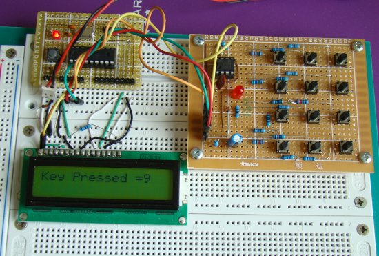
Today, I am going to share with you about a new keypad interfacing technique that uses only two I/O pins of a microcontroller: one for signalling the microcontroller when a key is pressed, and the other is to read the key information. It is based on a 555 timer IC which is configured as an astable multivibrator. I am not sure if anybody has ever tried using a 555 IC for keypad interfacing, but this technique really works. I am going to demonstrate this with a 4×3 keypad (a standard telephone dial pad). A PIC16F628A microcontroller will read the output of a 555 timer IC, determine what key has been pressed, and display it on a character LCD module.
Theory
This technique is based on a very simple principle. The output frequency of a 555 astable multivibrator is defined by two resistors and a capacitor, as shown below.
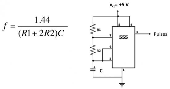
If we fix R1 and C, the frequency can be varied by varying R2. In this technique, each key on the keypad connects a different R2 resistor when it is pressed, and therefore, generates a different output frequency. The microcontroller can then read the output frequency and determine which key was pressed. At first it does seem more complex as it may require floating point math regarding the frequency calculations. Besides, the frequency may not be precisely stable all the time. But this can be simplified with the proper selection of resistors and the use of the timer module inside the microcontroller. So here’s how it works:
When a key is pressed, a certain value of R2 resistor is connected between pins 7 (Discharge) and 6 (Threshold) of the 555 timer, completing the astable multivibrator circuit. The output pulses are counted for 100 ms through a timer module (used as counter) in the microcontroller. The microcontroller determines the pressed key from the number of times the timer has overflown. If the timer module overflows 5 times, the pressed key is 5. Similarly, if 0 key is pressed, the timer doesn’t overflow in the 100 ms window. Isn’t it simple now?
Circuit diagram
The figure below shows how the 12 keys are connected to the 555 timer IC to generate 12 different frequencies. R0 through R# are 12 different resistors corresponding to those frequencies. You can see when a key is pressed, the corresponding resistor is connected between pins 6 (Threshold) and 7 (Discharge) and the astable multivibrator circuit is completed.
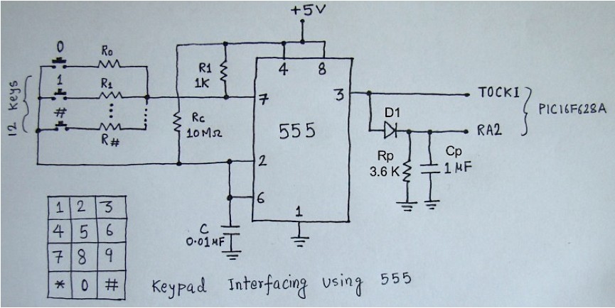
The values of R1 and C are 1 K and 0.01 uF. The following table shows the different values of R2 for each keys, the corresponding frequencies, and the number of times the Timer0 module overflows. Some of these resistors are made from combining two resistors together.
| R1=1K, С=0.01uF | ||||
| Key |
R2, Ohm |
f, Hz |
Pulses in 100 ms |
Timer0 Overflows |
| 0 | 47000 | 1515.79 | 151.58 | 0 |
| 1 | 22000 | 3200 | 320 | 1 |
| 2 | 12000 | 5760 | 576 | 2 |
| 3 | 8200 | 8275.86 | 827.59 | 3 |
| 4 | 5600 | 11803.28 | 1180.33 | 4 |
| 5 | 4700 | 13846.15 | 1384.62 | 5 |
| 6 | 3900 | 16363.64 | 1636.36 | 6 |
| 7 | 3400 | 18461.54 | 1846.15 | 7 |
| 8 | 2800 | 21818.18 | 2181.82 | 8 |
| 9 | 2530 | 23762.38 | 2376.24 | 9 |
| * | 2200 | 26666.67 | 2666.67 | * |
| # | 2000 | 28800 | 2880 | # |
So when the # key is pressed, the Timer0 module overflows 11 times.
Important Note: For more reliable operation of this circuit, use lower tolerance values for capacitor C and R2 resistors. I am using 5% tolerance for R2 and C, but lower than this would be better.
Part 2. Frequency and Pulse outputs, Significance of Rp and Cp values, Role of Rc resistor.