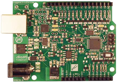
The Ruggeduino is a ruggedized Arduino-compatible microcontroller board (Figure 1). Features include overcurrent and overvoltage protection on all I/O pins and 5 V/3.3 V outputs, ESD protection on all I/O pins and USB port, total microcontroller overcurrent protection, and operation at up to 24 V. Fully assembled and ready to work right out of the box. Works with the Arduino GUI and is compatible with Arduino shields and libraries.
 |
|
| Figure 1. | Ruggeduino is a ruggedized Arduino-compatible microcontroller board. |
Who needs a Ruggeduino? Anyone who makes mistakes. There are some things a regular Arduino will tolerate; other actions will destroy it immediately. We took all the common mistakes that people make with their Arduinos and designed the Ruggeduino to protect against them. Everyone from students just getting started with electronics to busy engineers that can’t afford to have their tools fail them can benefit from a microcontroller board that forgives mistakes.
Think of it this way: one Ruggeduino costs much less than two Arduinos, and you don’t have to wait for the second one to arrive after you destroy your first.
Quick Look
The Ruggeduino is directly compatible with the Arduino UNO SMD. It uses the same microcontroller (ATmega328P), same Arduino GUI, same USB interface (ATmega16U2), same clock frequency, same connectors and connector positions, and so on. The Ruggeduino adds several features to make it more rugged, making sure that it will last a long time.
This Table 1 shows a quick comparison between the Arduino UNO SMD and the Ruggeduino.
| Table 1. | Quick comparison between the Arduino UNO SMD and the Ruggeduino. |
 |
|
Power In
The Ruggeduino is powered from one of three sources:
- USB port: 5 V is provided directly from the USB port. A 500 mA PTC (resettable fuse) protects the computer from overcurrent.
- DC power jack: a 2.1mm center-positive DC power adapter can supply 7 V - 24 V. This power input is also protected by a 500 mA PTC (only on the Ruggeduino!)
- Vin: this connector pin can either source power to the Ruggeduino (7 V-24 V) or draw power from the DC power jack.
When more than one power source is present, the automatic power switching circuit selects external power (DC power jack or Vin, whichever is higher) when available, otherwise USB power is used. This behavior is the same as the Arduino UNO.
Power Out
The Ruggeduino can supply power to shields or external circuits in three ways:
- +5 V output: the +5 V connector pin is the same voltage seen by the microcontroller. The current from this output is naturally limited by thermal protection on the on-board 5 V regulator when externally powered, or limited to 500 mA by a resettable fuse when USB-powered.
This +5 V output can typically source 500 mA when the DC power jack voltage (Vext) is 9 V or less, and less current as Vext increases due to thermal loading on the 5 V regulator.
On the Ruggeduino, the +5 V output is protected against applied high voltage. If, for example, you apply 24 V to this pin by mistake, the Ruggeduino will not be damaged. If you do the same thing on an Arduino UNO, you will destroy it!
- +3.3 V output: the +3.3 V connector pin sources 350 mA (Vext is 9 V or less). Note that this is quite a bit more than the 50 mA limit of the Arduino UNO.
As with the +5 V output, the +3.3 V output is protected against applied high voltage; if you apply 24 V to this pin by mistake, the Ruggeduino will not be damaged.
- Vin: the Vin connector pin can draw power from the DC power jack. This power output is limited to 500 mA by a PTC (resettable) fuse. The 500mA PTC fuse protects this output against conditions like short circuits to GND (which would damage an Arduino UNO).
Programming
The Ruggeduino is programmed in exactly the same way as the Arduino UNO; the full details can be found in the Programming section of the Arduino UNO SMD product page.
In summary:
- From the Arduino GUI, select “Arduino UNO” from the Tools->Board menu.
- The Optiboot bootloader is preloaded on the Ruggeduino so it is ready for uploading sketches.
- The LUFA DFU/serial bootloader is preloaded on the Ruggeduino so it is ready for uploading sketches. It can be modified or replaced in exactly the same way as the Arduino UNO: using DFU/FLIP or through the ICSP header.
- The ATmega328P can be programmed through the bootloader or through its ICSP header.
- The Ruggeduino uses the same auto-reset mechanism as the Arduino UNO. Jumper J3 can be cut to disable this.
Installation
No special installation steps are required on Linux or Mac OS X. The Ruggeduino is recognized as a Communication Device Class (CDC) USB device and appears as a standard serial port on your system.
On Windows, this INF file must be installed to tell Windows that the Ruggeduino is a CDC USB device. Follow the instructions on the Getting Started with Arduino page. Just remember to use the INF file for the Ruggeduino instead of the one for the Arduino UNO. There is no conflict between the two INF files; it is OK to have a mix of Arduino UNO and Ruggeduino boards all plugged in at the same time.
Protection Details
The Ruggeduino was designed to withstand common electrical mistakes, thus ensuring your Ruggeduino will last a long time. This section describes the details of these protective circuits.
I/O Pin Protection
Every I/O pin is protected by a 5.1 V zener diode and 220 ohm 30 mA PTC (resettable fuse). The equivalent circuit is shown in Figure 2.
 |
|
| Figure 2. | The equivalent circuit of Ruggeduino I/O Pin Protection. |
This protection circuit means:
- Every I/O pin can have up to 24 V applied to it and will still not be damaged.
- Every I/O pin can be short-circuited to ground and will still not be damaged
- Every I/O pin can be short-circuited to another I/O pin and will still not be damaged
In addition, the 220 ohm PTC can take the place of series resistors in many applications, such as lighting LED’s, driving transistors, and so on. Here is an example of an Arduino driving a transistor through a series resistor, and how the Ruggeduino simplifies the circuit due to its built-in 220 ohm series resistance (Figure 3).
 |
|
| Figure 3. | Ruggeduino simplifies the circuit due to its built-in 220 ohm series resistance. |
Similarly, you can connect LED’s directly to Ruggeduino digital outputs without any resistors and not worry about destroying them due to excessive current (Figure 4).
 |
|
| Figure 4. | You can connect LED’s directly to Ruggeduino digital outputs without any resistors. |
If you do have an application where this built-in 220 ohm resistance is not wanted, you can easily change it. Every I/O pin has through-hole pins surrounding its PTC fuse that can be jumpered with either a wire for 0 resistance or with a standard resistor (Figure 5). Here is a picture showing how to bypass the 220 ohm PTC for pin D7.
 |
|
| Figure 5. | Every I/O pin has through-hole pins surrounding its PTC fuse that can be jumpered with either a wire for 0 resistance. |
Total Microcontroller Current Protection
It is not enough to limit the current of each I/O pin, the total current sourced by the microcontroller must also be limited to limit its power dissipation. Current-limiting device IC3 on the schematic does this: the microcontroller total current is limited to 150mA (typical) no matter how many pins are sourcing current (Figure 6).
 |
|
| Figure 6. | Current-limiting device IC3: The microcontroller total current is limited to 150mA no matter how many pins are sourcing current. |
The MIC2009A limits the current from the +5 V input to the +5 v/1 output, which is used to power the ATmega328P. As soon as the ATmega328P pins start sourcing more than 150 mA the +5 V/1 voltage is automatically reduced by the MIC2009A to limit the current to this level. You can short every one of the ATmega328P’s I/O pins to ground and set them all high in your program and you still won’t destroy the microcontroller. Don’t try that with an Arduino!
5V Output Protection
The 5 V output connector pin is current-limit protected by the thermal shutdown feature of the on-board 5 V regulator. In addition, this pin is protected against applied overvoltage. Any voltage at this pin above 5.5 V (typical) will disconnect the pin from the rest of the Ruggeduino circuitry, preventing this damaging voltage from reaching the other components.
Applied voltages of up to 24V are blocked.
The schematic below (Figure 7) represents the output protection circuitry. The comparator is constantly checking the output pin +5 VIO against a reference voltage set by the 2.4 V zener diode. If the +5 VIO voltage becomes too high, the comparator trips and turns off the MOSFET to disconnect the microcontroller’s +5 V supply from the overvoltage applied at +5 VIO.
 |
|
| Figure 7. | +5V output protection circuitry. |
3.3 V Output Protection
The 3.3 V output connector pin is current-limit protected by the thermal shutdown feature of the on-board 3.3 V regulator. In addition, this pin is protected against applied overvoltage. Any voltage at this pin above 3.6 V (typical) will disconnect the pin from the rest of the Ruggeduino circuitry, preventing this damaging voltage from reaching the other components.
Applied voltages of up to 24 V are blocked. A circuit similar to the one shown above for 5 V output protection is used.
Vext Fuse and Vin Blocking Diode
The external DC power jack input is fused on the Ruggeduino (500 mA PTC resettable fuse). The main purpose of this fuse is to protect the Vin output when used to provide power to external devices. The on-board 5 V regulator provides additional current limiting (thermal limiting) to the Ruggeduino circuitry.
On the Arduino Uno, the Vin output pin has no reverse blocking diode. If you apply power to the Arduino through this pin and reverse the voltage by mistake, you will destroy the Arduino. On the Ruggeduino the blocking diode comes after the Vin input thus prevents this failure mode.
 |
|
| Figure 8. | Vin and Vext protection circuitry on the Ruggeduino. |
The schematic below (Figure 8) shows the Vin and Vext protection circuitry on the Ruggeduino.
RESET Pin Protection
The microcontroller RESET pin is protected by a 1k series resistor (R15 on the schematic) to limit current into this pin in the case of applied overvoltage.
AREF Pin Protection
The microcontroller AREF pin is protected by a 600 ohm series resistor (R14 on the schematic) to limit current into this pin in the case of applied overvoltage.
USB Connector Protection
The USB data lines are protected against ESD by low-capacitance transient voltage suppressors (TVS), as is the USB power line.
ICSP Pin Protection
The ATmega8U2 ICSP pins are protected by 1k series resistors and 5.1 V zener diodes. The ATmega328P ICSP pins have the same protection as the other I/O pins on the microcontroller (see above).
Other Features
Accurate Clock
The ATmega328P on the Ruggeduino is clocked by a highly-precise 16 MHz oscillator (0.005% accuracy) rather than the resonator used on the Arduino Uno.
D13 LED Isolated
The LED connected to D13 is isolated by a transistor circuit rather than being driven directly from the ATmega328P pin. This isolation draws much less current from the ATmega328P pin allowing it to be used for other purposes.
LED Disconnect Jumpers
In low-power applications, the on-board LED’s can be an unnecessary source of wasted current. All four of the Ruggeduino LED’s have cuttable jumpers in series (J1, J2, J4, J5) which can be cut to disable the associated LED. The jumpers can be reconnected using a 2-pin jumper and shunt, or bridged with solder or a small wire.
ATmega16U2 Reset Switch
For reprogramming the ATmega8U2 USB microcontroller, solder in switch S2, a standard 6×3.5 mm tactile switch. This makes it easy to put the ATmega8U2 microcontroller into firmware update mode.
DTR Current Limit Resistor
The auto-reset mechanism on the Arduino Uno can be stressful to the ATmega8U2 USB microcontroller since it has to instantly discharge the coupling capacitor that connects to the ATmega328P reset pin. This instantaneous current can, over time, degrade the pin driver and possibly even cause it to fail. On the Ruggeduino, 100 ohm resistor R41 limits this current and protects the ATmega8U2.
Downloads
Schematic of the Ruggeduino - download