Kris Lokere, Linear Technology
EDN
Introduction
The “Internet of Things” refers to a growing trend to connect not only people and computers, but all sorts of “things” to the Internet. In applications such as industrial plants or large infrastructure projects, connecting more sensors (or actuators) in more places can increase efficiency, improve safety, and enable entirely new business models.
Rather than the challenge and expense of running cables all around a factory, it is now possible to install reliable, industrial-strength wireless sensors that can operate for years on a small battery, or even harvest energy from sources that are already available, such as light, vibration, or temperature gradients.
Linear Technology offers all the components needed to design high-performance, reliable, low power wireless sensor networks. This case study shows a real-world design that combines a high-resolution temperature sensor, a power management circuit that uses solar energy when available and battery backup when needed, and a low-power radio module that automatically forms a reliable mesh network to wirelessly connect all sensors to a central access point.
Design Overview
Figure 1 shows the block diagram of the design. The temperature sensor is based on a thermistor biased by a low noise LT6654 voltage reference. The 24-bit delta-sigma ADC LTC2484 reads the thermistor voltage and reports the result via SPI interface.
 |
|
| Figure 1. | A Wireless temperature sensor is formed by connecting a wireless radio module to an ADC, reference and thermistor. The circuit is powered by an energy harvester that can take power from a battery or solar panel. |
The LTP5901 is the radio module that contains not only the radio, but also the networking firmware needed to automatically form an IP-based mesh network. In addition, the LTP5901 has a built-in microprocessor which reads the LTC2484 ADC SPI port, and manages the power sequencing for the signal chain components.
The LTC3330 is a low-power dual switch-mode power supply that derives power from the solar panel when enough light is available and reverts to using the battery when needed to maintain output voltage regulation. The LTC3330 also includes an LDO which is used to duty-cycle power to the temperature sensor.
Signal Chain
This design uses a thermistor to measure temperature. Thermistors are well suited to read temperatures in a range well beyond typical ambient temperatures of interest to humans. Thermistors are resistors with a strongly negative temperature coefficient. For example, part number KS502J2 (by US Sensor) is 5k at 25 °C and changes from 88k to 875 Ohm over the -30°C to +70°C temperature range.
The thermistor is connected in series with two accurate 49.9k resistors, and biased up by precision voltage reference LT6654 (Figure 2). The LTC2484 delta-sigma ADC measures the resistor divider ratio with 24-bit resolution. The ADC total unadjusted error is 15 ppm, which for this thermistor slope corresponds to a temperature uncertainty of less than 0.05°C. This thermistor is specified with an accuracy of 0.1 °C, so that without any calibration we can measure the temperature to that accuracy.
 |
|
| Figure 2. | LTC2484 24-bit ADC reads the thermistor voltage. Because the input common-mode voltage remains centered, the Easy Drive ADC draws no input current, which makes for an easy and accurate ratiometric reading. |
The ADC noise is less than 4 µVpp, which corresponds to less than a 0.005 °C change in temperature. Therefore, with a calibration step, this system could be used to measure temperature to extremely fine resolution. Since the ADC measures the ratio of thermistor voltage to reference voltage, strictly speaking the reference does not need to be accurate. However, it must be low noise, because variations in reference voltage during the ADC conversion period could produce errors.
The LTC2484 ADC features an Easy DriveTM input structure. This means that net differential sampling currents during a conversion period are nearly zero. As a result, no measurement errors are induced from input sampling current flowing through the resistive thermistor network, which means no separate op amp buffer is needed. Bypass capacitors provide a low impedance path at high frequency. In many cases it is not needed to measure temperature constantly, but rather once per second or even just once per minute. It makes sense to save power during the times that the system does not measure temperature. This application circuit does exactly that, as described below.
The resistor network draws up to 25 µA from the 2.5 V reference. To avoid this power loss between measurements, the power supply to the reference is duty-cycled to be on only during measurements. The RC time constant at the input of the ADC is about 5 msec. By turning on the power 80 msec prior to taking a measurement, full settling at the ADC input is ensured.
In fact, since both input nodes turn on at the same slope, readings are accurate well before the theoretical settling time. The LT6654 is powered from the 3 V LDO output of the LTC3330. The LTP5901 microprocessor drives the LDO enable pin of the LTC3330 high and low at the correct times before and after performing a temperature reading.
The LTC2484 automatically enters sleep mode when not converting. The 1 µA sleep current is low compared to the already low power of the wireless radio. Therefore, it is not necessary to duty-cycle the power supply to the ADC. By keeping the ADC permanently powered from the same supply voltage as the LTP5901, the logic levels at the SPI interface are ensured to be the same, which helps keep the design simple.
After providing a conversion result through the SPI port, the LTC2484 automatically starts a new conversion, and stores the result in its internal register until the user asks to read it again. This can be handy in systems that require temperature to be read very frequently. However, some ultra-low power applications may wait a long time in between readings. To ensure that the temperature that is communicated to the user is always a ‘fresh’ reading, this application first toggles the /CS and SCK pins to flush-out the ‘stale’ temperature reading from the ADC register.
This automatically starts a new temperature conversion. The microprocessor waits until the conversion is completed, and then reads the result through the SPI port. Even though a new temperature reading will automatically start again, the system proceeds to shut down the thermistor network (by turning off the LDO) since the result of this extra reading will be subsequently ignored.
The overall power consumption of the temperature sensor circuitry can be estimated as follows. First, sum the current of the reference (350 uA), thermistor network (25 µA), and ADC (160 µA when converting) for a total of 535 µA (see Table 1). Then, consider how long this current will be on. The ADC takes about 140 msec for a conversion, and prior to that we wait 80 msec for the reference and thermistors to settle.
| Table 1. | Signal Chain Current Consumption (when active) |
||||||||
|
|||||||||
Add in some time for the SPI readout, and we are at about 300 msec on-time. To consume a current of 535 µA during 300 msec corresponds to a charge of 160 µC. We should add to this the charge needed to charge up the 4.7 µF supply bypass capacitor to the voltage reference, because this node gets recharged from 0 V to 3 V with every reading.
This 14 µC of charge brings the total to 174 uC per temperature reading. If we take one temperature reading every 10 seconds, this works out to an average current consumption of 17 µA. Other examples of average supply current are given in the Table 2.
| Table 2. | Average Signal Chain Current Consumption Based on Read Frequency |
||||||||
|
|||||||||
The LTC3330 manages all the power for this application. It includes two switch-mode power supplies and one linear regulator in a small monolithic package. A buck-boost converter can take power from the battery to maintain a regulated output voltage (set to 3.6 V for this application).
 |
|
| Figure 3. | The LTC3330 takes power from the solar panel or battery, automatically prioritizing between the two sources to maintain a regulated output voltage. An additional LDO output is controlled by a logic input pin, which is used to duty-cycle power to the temperature sensor. The LTC3330 generates an output flag to indicate whether solar or battery power is being used. |
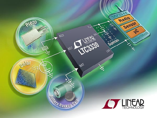
A separate buck converter can take power from the solar panel to also regulate the output voltage to the same level. An internal prioritizer ensures that solar power is used when possible and only draws power from the battery when needed (Figure 3). For other applications, the LTC3330 also supports AC energy harvesting sources such as piezo crystals which generate an AC voltage proportional to vibrational energy (see Figure 4).
 |
|
| Figure 4. | The LTC3330 energy harvesting DC/DC battery life extender harvests energy from piezoelectric, solar or magnetic sources. |
The LTC3330 draws less than 1 µA quiescent current, making it suitable for this low power wireless application. The power loss in the power supply is only a small fraction of total power loss so that most of the power is available for the “load,” which is the temperature sensor and wireless network.
In addition to the two switch-mode power supplies, the includes an LDO with a separate LDO enable pin. This feature is handy for these duty-cycled applications. The voltage reference and thermistor network are powered from the LDO. This not only reduces switching noise, but it also allows the application to toggle power to the signal chain on and off, while keeping power to the wireless radio always on.
Even though the wireless radio does not consume much power in between transmissions, it is essential that it always remain biased up to keep timers running correctly so that the entire network will remain time-synchronized. The microprocessor inside the wireless radio sequences the LDO enable pin at the correct times to prepare the signal chain for a temperature reading.
The LTC3330 provides an output flag (EH_ON) which tells the system whether power is being drawn from the battery or from the solar panel. It can be informative for the end user to have real-time access to this information. Therefore, we let the microprocessor inside the wireless radio read this output flag and transmit it through the network, along with the temperature data itself.
The logic level for this EH_ON output is referred to an internal bias voltage of the LTC3330, which varies depending on operating mode and can be higher than 4 V. Rather than connecting that output pin directly to the lower-voltage logic input of the wireless radio, we divide it down and feed it into a built-in 10-bit ADC that is part of the microprocessor. In this case, we just use that ADC as a comparator to indicate which power source the LTC3330 is using.
Wireless Networking
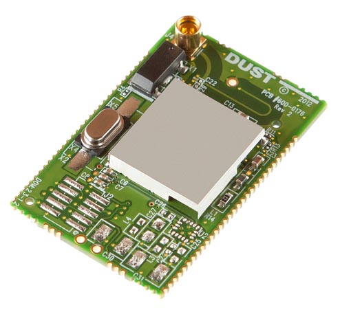
The LTP5901 is a complete wireless radio module, which includes the radio transceiver, embedded microprocessor, and networking software. The physical format is that of a small printed circuit board (Figure 5), which can be easily soldered onto the main circuit board that contains the rest of the application (signal chain and power management).
 |
|
| Figure 5. | The Complete Wireless Radio Module LTP5901. |
The LTP5901 performs two functions in this application: wireless networking and housekeeping microprocessor (Figure 6). When multiple nodes of LTP5901 are powered up in the vicinity of a network manager, the nodes automatically recognize each other and begin forming a wireless mesh network. The entire network is automatically time-synchronized, which means that each radio is powered on only for very short, specific time intervals.
 |
|
| Figure 6. | The LTP5901-IPM requires remarkably few connections to run this entire application. All wireless networking functions, including firmware and RF circuitry, are already built in. A 3-wire SPI master talks to the LTC2484 SPI port. A GPIO pin (DP2) controls the power sequencing to the sensor. The built-in ADC acts as a convenient level translator to read the energy harvesting status flag EH_ON from the LTC3330. |
As a result, each node can function not only as a source of sensor information, but also as a routing node to relay data from other nodes toward the manager. This creates a highly reliable, low power mesh network, where multiple paths are available from each node to the manager, even though all nodes, including the routing nodes, operate on very low power. A typical range for this radio technology is 100 m between nodes, with even more range possible in favorable outdoor conditions.
The LTP5901 includes an ARM Cortex-M3 microprocessor core, which runs the networking software. In addition, this core can be programmed through user-supplied firmware to perform tasks specific to the user application. As a result, many applications can be built without needing any third-party microprocessor.
In this example, the microprocessor inside the LTP5901 manages the power sequencing to the temperature sensor by turning the LDO of the LTC3330 on and off at the correct times, so as to conserve power between temperature readings. The LTP5901 communicates directly to the SPI port of the 24-bit ADC which reads the temperature sensor.
Finally, the LTP5901 reads the power status output flag (EH_on) from the LTC3330, which indicates whether solar light or the battery is used to power the circuit.
Power consumption of the wireless radio can be estimated using the online SmartMesh® Power and Performance Estimator tool on Linear Technology’s website at this link [1]. For a typical network of 20 motes, where 10 motes have a direct wireless connection to the manager (1-hop), and 10 others have an indirect connection to the manager (2-hop), average power consumption is about 20 µA for the 2-hop nodes and 40 µA for the 1-hop nodes.
These figures are for each node reporting temperature once per 10 seconds. The reason that the 1-hop nodes consume about twice as much power is because they transmit not only their own sensor data, but also act as routing nodes to forward the sensor data from some of the 2-hop nodes. The power levels mentioned above can be further reduced by about a factor of two if a feature called ”advertising” is turned off. Once advertising is turned off, the network will no longer recognize new nodes that want to join the network. Other than that, there is no impact on network operation.
Overall Power Consumption
The total power consumption of the complete application circuit depends on various factors, including how often each sensor measures temperature and how the nodes are configured in the network. Typical power consumption for a sensor node reporting once per 10 seconds is less than 20 µA for the sensor portion and can be 20 µA for the wireless radio, for a total average load current of about 40 µA.
А small 2 inch by 2 inch solar panel (for example Amorton series) can generate 40 µA at even relatively moderate indoor lighting conditions (200 lux), and much more in bright light. This means that this application could run entirely on power from the solar panel in many conditions. If the circuit is in the dark and needs to run entirely on battery power, a 2.4 Ah AA battery (such as the Tadiran XOL series) could power this application for almost 7 years. In low or variable light conditions, the circuit automatically toggles back and forth between use of solar power and battery power, so that any available solar power is used to extend battery life.
Conclusion
Linear Technology’s signal chain, power management, and wireless networking products enable the design of complete, truly wireless sensor network products. The time-synchronized wireless mesh network ensures that minimal power is used to reliably transmit data from node to node. The on-chip microprocessor can duty cycle power to the sensor circuitry. Efficient, highly integrated power management ICs can power the application entirely from a small solar panel or for many years from a small battery.
References