Digital control inside an on-board power supply facilitates improved efficiency, reduced total cost and advanced system power management. The following is from an Ericsson white paper and is very relevant to Digital Power.
Digital techniques in power conversion
The concept of “digital power” has received significant attention and promotion in the past few years, from both semiconductor suppliers and power supply manufacturers. There is a need to explain the concepts of digital power; explore the advantages and tradeoffs of digital techniques compared to analog approaches; discuss some of the standardization directions; and explore the possibilities for digital power.
Digital power is defined and implemented differently by various suppliers; moreover, there is not yet an appreciable field history of successful large-scale designs using digital approaches. The result is an atmosphere of uncertainty and some confusion about digital power. Is it cost effective? How does its performance compare to conventional analog approaches? Is it reliable? Does it affect the complexity of the design and development process? Are developers with specialized skills needed? How “standardized” is it and will it affect second sourcing?
A more proactive stance is needed in defining the process to enable the implementation of power supplies and systems using digital power. Most importantly, the above questions must be answered so that the end user – a system integrator or original equipment manufacturer (OEM) – can work confidently with digital power.
Why is power conversion still mostly in the analog domain? The main reason is that efficiency is vital for most power system applications. No matter how many “bells and whistles” going digital might add, if it detracts from efficiency it will have limited appeal. The added power dissipation “overhead” in the form of additional circuitry for digital controls made this approach quite unattractive until very recently.
Cost and packaging density are also issues. Happily, the advent of a mature complementary metal oxide semiconductor (CMOS) digital technology has solved these issues by providing digital processing with high density, negligible power dissipation at low cost.
Digital control and management
“Digital power” is a broad term that encompasses several concepts and subdisciplines, and the end user can benefit from digital power on several different levels. One of the major features of digital power is that for any given system application, the end user will typically select only a subset of the available digital power solutions. This decision will be based on factors such as cost, complexity and system availability and maintenance requirements.
One key concept is the distinction between power control and power management. The term “power control” is used to address the internal control functions in a power supply, especially the cycle by-cycle management of the energy flow. Note that a power supply using digital power control techniques will appear identical to the end user as a power supply using analog power control techniques.
The term “power management” is used to address communication and/or control outside one or more power supplies. This includes functions such as power system configuration, control and monitoring and fault detection. Presently, these functions tend to be a combination of analog and digital. Digital power management implies that all of these functions are implemented with digital techniques and some type of data communications bus structure.
Power supply control
A classic analog power supply control loop is shown in Figure 1. A pulse width modulator (PWM) integrated circuit (IC) is used as the primary control element. The power supply output voltage is sampled by means of a resistive voltage divider and compared with a DC reference voltage by an error amplifier.
 |
||
| Figure 1. | Block diagrams of analog and digital control systems depicted together with some parts of the power train. |
|
The error amplifier output signal is used by the PWM to control the “on time” of the power switch.
For loop compensation, which is needed to ensure the proper balance of dynamic response and stability, a fixed resistor and capacitor network is typically used external to the PWM IC.
Two other major sections of the power supply are the input and output filter networks. These sections, composed of inductors, capacitors and resistors, provide several functions. The input filter helps protect the power supply from transients in the supply voltage, provides some energy storage for power supply operation during dynamic load changes, and includes filter networks to allow the power supply to meet its input conducted emissions specifications.
The output filter provides smoothing of the output voltage to ensure that the ripple and noise specifications are achieved and also contains energy storage for servicing dynamic current requirements of the load circuits. It is important to note that the input and output filters and the power devices remain essentially the same with either an analog or a digital control structure.
Figure 1 depicts the structure of a typical digital power supply control system.
The sensing of the output voltage is similar to that in an analog design. Rather than an error amplifier, however, the sensed analog voltage is converted to a binary digital number with an analog to digital converter (ADC). The digital outputs from the analog to digital converter (ADC) are fed to a microcontroller (µC) that provides the processing. On board read-only memory (ROM) program memory is used to store the control algorithms for the µC.
These algorithms allow the µC to perform a series of calculations on the digital outputs from the analog to digital converter (ADC). The results of these calculations are such parameters as the error signal, the desired pulse widths for the drivers, optimized values for delay in the various drive outputs, and also the loop compensation parameters. The external loop compensation components used with the analog system are no longer needed.
All values of parameters such as output voltage, output current and temperature are stored in electrically erasable programmable read-only memory (EEPROM) at manufacturing or via transfer with a communications bus. The EEPROM content is downloaded to the random access memory (RAM) during power-up, and the µC then uses this part of the memory for read and write operations.
Digital control is considerably more flexible than analog control in its ability to adapt to changes in line and load conditions. It has the ability to change the control parameters as a function of the power supply operating conditions. This is illustrated by the following examples.
In a synchronous buck power supply, the top and bottom metal oxide semiconductor field-effect transistors (MOSFETs) are operated so that both never conduct simultaneously. This is guaranteed by defining a “dead time” period after one of them is turned off and before the other is turned on. With digital control the dead time does not need to be fixed, but can be varied via a digital control loop as a function of operating conditions to optimize the power supply efficiency. This technique is especially valuable at low load as shown in the comparison in Figure 2.
 |
||
| Figure 2. | A parameter such as “dead time” in a synchronous buck power supply may be optimized over line and load conditions to improve efficiency |
|
In analog control designs, the feedback loop compensation is a compromise between stability and dynamic response performance. Using digital control techniques, it is possible to construct non-linear, or adaptive, control loops that change the compensation as a function of operating conditions. That is, the power supply displays fast response when it needs to and slower response in other situations.
Figure 3 shows examples of this adaptive behavior. In addition to the enhanced dynamic response, this approach has other benefits to the power system. Fewer output decoupling capacitors are required to ensure a given voltage tolerance, with resulting savings in cost and component space. Nonlinear control can also be used to allow power supply operation in discontinuous mode without the usual disadvantage of poor dynamic performance.
 |
||
| Figure 3. | Non-linear, or adaptive, control loops can combine the benefits of stability and responsiveness. |
|
Because of advantages such as those described above, digital control is now the preferred approach and will gradually be used more and more for new power supply designs. The fact that some of the embedded digital control circuitry in the power supplies can be used for system power management purposes is an added bonus. Therefore, much of the hardware for the power management capability that will be described in the next section comes “for free” as far as the system designer is concerned.
Power system management
Digital power management offers several benefits and opportunities and can be used at several different stages of the power supply and power system life cycle. Flexibility is the key; the power system designer may pick and choose only those features and capabilities that are important to a specific application:
During manufacturing of the power supply, automated test equipment (ATE) control can be used to configure parameters such as output, voltage trimming, protection trip points and loading of date codes and serial numbers.
During optimization of the power system design, the digital interface can be utilized to measure temperature, voltage and output currents and to set the trip points for fault protection circuits.
During assembly and testing of the board and system, the digital power management interface can be used by an ATE.
With a power system host control, start-up and shut-down sequencing can be provided. Operating temperatures can be monitored to regulate the cooling fans and fault detection, and management routines can be developed that take into account conditions elsewhere in the system.
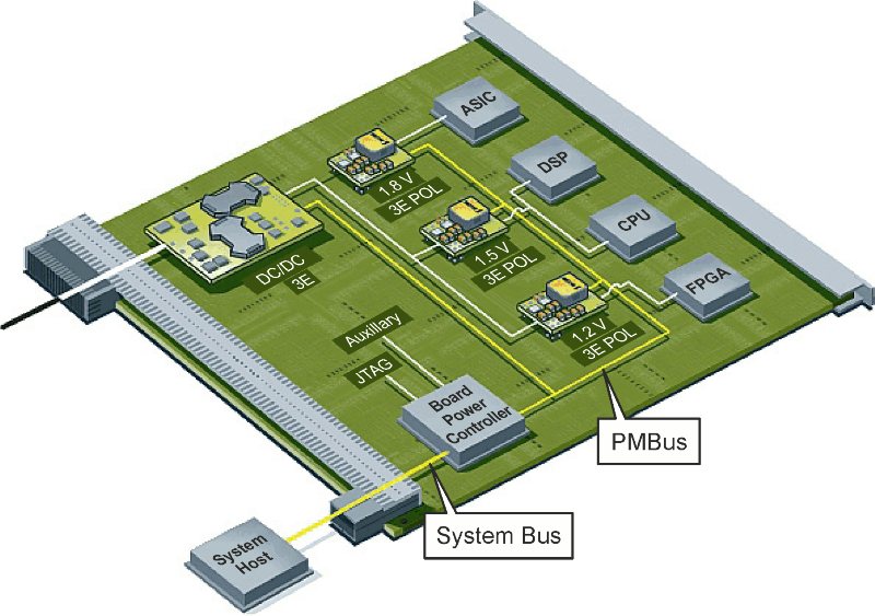
The digital power management system has a basic architecture consisting of power supplies that communicate with a centralized power system host control via a digital communications bus as described in Figure 4.
 |
||
| Figure 4. | A digital power management system consisting of power supplies (slaves) connected to a controller (master) via a communications bus depicted by the yellow lines. |
|
The power supplies are DC/DC converters or point of load (POL) regulators. The control device can take many forms, including:
- An IC dedicated to power system control
- A general purpose microcontroller
- A laptop computer with a graphical user interface (GUI)
- ATE during the power supply or system testing process.
The host device has a control domain consisting of a single system board, and for some larger scale systems, this host will in turn interact with higher system level controllers.
System power control is becoming more complex as the number of voltage levels on a typical board increase. This greatly increases the complexity of the voltage sequencing.
Sequencing order, ramp times and delays need to be controlled for both normal start-up and shutdown operation as well as for some fault conditions. All this is straightforward with digital management without resorting to installing analog control and timing components or even using a soldering iron (Figure 5).
 |
||
| Figure 5. | The sequencing order for start-up and shut-down of multiple power supplies can be controlled using digital power management. |
|
Voltage margining is another example of using digital management for power supply control. This is used during the final stages of production to verify the robustness of the unit. Voltages are varied by perhaps ±5 percent in different combinations (Figure 6). Using the digital communications bus, this can be accomplished in less than a second without any additional hardware or interconnections.
 |
||
| Figure 6. | Digital power management can be used for voltage margining of the output from the power supply (corner testing). |
|
A common requirement that falls into the configuration category is programming thresholds for fault detectors. Using a digital bus results in extreme flexibility:
- Temperature protection can be set, and operation can be configured digitally for either latching or automatic restart.
- Over current protection can be set, and latching or automatic recovery modes can be programmed.
- An over voltage protection trip point for a specific output voltage trimming and latching is easily programmed, as are automatic recovery modes.
Monitoring consists of measurement of such parameters as input and output voltages and currents, operating frequency, and temperatures interior to the power supplies. Most OEMs will find this capability to be of the greatest use during the design and evaluation phases of a new system.
Digital monitoring allows for all of these measurements to be made via a laptop computer and GUI rather than with thermocouples, soldering irons and component replacements. Gaining parametric information at this stage allows for optimization of the power system and for the selection of the most cost-effective power supplies.
Designers of high-end and high-availability systems may want to incorporate these kinds of capabilities in the final product, so that parametric data can be collected in the system operating environment. Examples of capabilities with this approach are:
- Efficiency may be monitored and degradation noted prior to actual failure so that part replacements can be made without affecting system availability.
- System fan speed can be controlled as a function of actual temperatures inside power supplies.
- A complete field population of systems can be queried to find the locations of power supplies with a particular serial number, in order to replace a suspect batch of power supplies before the advent of field failures.
Most users will not need to use this degree of sophistication in their designs. An intermediate approach is to use an interrupt-driven design.
 |
||
| Figure 7. | Limits for both warning and fault conditions can be programmed for parameters such as temperature, output voltage and output current. |
|
Here, the host controller does not do routine monitoring of parametric data, but is only notified by a power supply when it is experiencing a problem (Figure 7). The host can then take the required action as a function of the power supply fault mode.
PMBus
The Power Management Bus (PMBus) is an existing protocol that has been adopted and supported by several power supply manufacturers. The protocol is owned by the System Management Interface Forum (SMIF).
Membership of SMIF is open to all interested parties, and the PMBus specification is freely distributed and is available for use on a royalty-free basis.
The PMBus is a broad, generic and flexible interface that can be applied to a wide range of devices, and it works well with all kinds of power supplies.
The PMBus addresses the host to the controlled device communication architecture described earlier and does not include provision for direct device to device communication. PMBus provides a dependable and widely used and understood digital power control and management interface without limiting innovation with other advanced techniques.
In its most basic form, the PMBus is a two wire serial bus that is based on the System Management Bus (SMBus), which is a derivative of the popular Inter-IC (I2C bus), but enhanced to provide greater functionality for power control applications.
The physical implementation is not defined by the PMBus. Power supply manufacturers and industry organizations, such as the Distributed-power Open Standard Alliance (DOSA) and Point of Load Alliance (POLA), are therefore cooperating to establish standard configurations for form factors, pin outs and mechanical interfaces for the connections and programming pins.
Conclusion
Digital power techniques have been proposed for some years now, but have not been able to successfully compete with analog solutions. Thanks to an increase in IC density, hard work on the part of semiconductor suppliers and a mature and reliable CMOS technology, digital processing for power conversion applications is now very attractive. Most importantly, the use of digital techniques results in capabilities and performance levels at both the power supply and system levels that are not possible with analog techniques.
While much of the publicity and controversy about digital power techniques is focused on power system management issues, the most important issue, and the ultimate driver for its acceptance, will be the benefits that it brings to the power supply itself. These benefits are real, measurable and available with today’s technology:
- Improved efficiency
- Improved reliability due to higher integration of digital control circuitry
- Reduced system cost because of fewer decoupling capacitors due to enhanced load transient response of adaptive digital control
- Increased power supply power density due to smaller digital control circuitry
- Tighter output voltage tolerances due to enhanced initial set point trimming
- Lower overall cost of ownership due to the above improvements.
Due to the cost parity between digital and analog control implementations using today’s technology, these benefits are “free” to the end user and represent real customer value.
There are sound advantages in utilizing the digital interface to power supplies during the system design, development and evaluation periods. The communications bus allows for complete user customization, and the net result is a reduction in design time, facilitated power management and a resulting reduction in time to market for the end product.
The user customization also allows a single power supply part number to serve several purposes, thereby reducing the inventory, the number of part numbers being managed, and the time required for sourcing power supplies.
References
- Bob Carroll, Primarion. Digital Power Forum 2005. The Next Steps for Digital Control [16 page presentation, hand-out on CD]
- Ericsson. September 2006. Performance Improvements for OEM System Designers: A Digital Control Case Study. [Online]
- Power Management Bus™ (PMBus™) Implementers’ Forum
- System Management Interface Forum (SMIF)
- Torbjörn Holmberg, Per-Johan Wiberg. Digital Power Forum 2006. Real Performance Improvements for OEM System Designers: A Digital Control Case Study [Hand-out on CD]. POWER SUPPLIES GO DIGITAL GLOSSARY REFERENCES