By Ivan Serrano
EEWeb
For most embedded designers, light-emitting diodes (LEDs) are simple components that are used as visual indicators. They typically involve a minimal circuit, and controlling the LED is typically only a matter of toggling the right logic level on a microcontroller's output pin. However, when you're in the business of making architectural model lighting, LEDs became more complicated.
In this case, you'll have to deal with turning hundreds of LEDs on or off from a single control point. You'll also have to consider the associated heat dissipation arising from the high current (a single LED doesn’t use much current, but things add up when you start to use hundreds or thousands of devices).
As an alternative to using lots of discrete LEDs, which will have to be controlled individually, you could decide to work with intelligent strips featuring LED modules like the WS2812B. Today's architectural model makers are no longer contented with simple LEDs that do nothing but glow in one color; instead, they seek the range of color and addressability that modules like the WS2812B can provide.
WS2812B-Based LED Strips
The WS2812B is a popular intelligent LED module that comprises RGB LEDs and their associated control circuitry, all integrated in a single 5050 SMD package. Each module has only four connections: VCC (5 V), GND, data-in, and data-out. It requires a voltage supply of 5 V to power up. The power consumption of each module can reach 50 mA when all three of its R, G, and B LEDs are fully turned on.
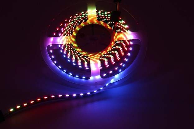
The individual WS2812B modules are daisy-chained (connected) to each other along the strip, and multiple strips can be connected as well (Figure 1). Each of the RGB LEDs inside a WS2812B module can be assigned a value from 0 to 255 in decimal (0x00 to 0xFF in hexadecimal). As with any RGB LED, this gives a total combination of 16,777,216 color variations.
 |
||
| Figure 1. | A strip of WS2812B LED modules displaying various colors (Source: pixabay.com) |
|
In a simple "PWM controlled" RGB LED strip, a single PWM signal, is applied to all of the red LEDs, a second PWM signal is applied to all of the green LEDs, and a third PWM signal is applied to all of the blue LEDs. This means that all of the modules in the strip end up displaying the same color.
By comparison, each WS2812B module contains three PWM functions, one for each of the RGB LEDs. This means that each module can display its own color, and all of the modules can display their colors simultaneously.
This makes these strips ideal to light up the various transportation modes in architectural landscape models, for example, where they are required to not only operate in running light mode, but to also employ different colors to highlight specific ideas. Of course, one could argue that using individual colored LEDs would achieve the same result, but a strip of WS2812B modules require only a single data line from the microcontroller, as compared to the hundreds or thousands of connections that may be required if using individual LEDs.
WS2812B Timing
While the hardware connections between WS2812B modules is simple – power (5 V and GND) and data (the data-out signal from one module drives the data-in signal to the next module in the chain) – the same cannot be said for the communications protocol. The WS2812B modules use an NRZ protocol on a single data connection. A data packet containing the RGB values is sent at a rate of 800 Kbps.
 |
||
| Figure 2. | Representation of the 1 and 0 NRZ code for the WS2812B (Source: SeeedStudio.com) |
|
Following a reset (RET or RES) period where the data signal is held low for more than 50 µs, the data packet is transmitted. As shown in the Figure 2, both 0 and 1 bit codes commence with logic 1 values; the difference between them is the relative duration of the high (TxH) and low (TxL) values (Table 1).
| Table 1. | Data transfer timing table (Source: SeeedStudio.com) | ||||||||||||||||||||||||
|
|||||||||||||||||||||||||
As the color of each RGB LED is specified using 8 bits, it takes 24 bits to define the color of each WS2812B module. The Figure 3 shows the 24-bit sequence associated with a single WS2812B module. The data is sent in the order G-R-B, with the most-significant bit (MSB) being transmitted first.
 |
||
| Figure 3. | 24-bit data packet for a WS2812B module the green MSB (G7) is transmitted first (Source: SeeedStudio.com) |
|
As we previously noted, each WS2812B module requires 24 bits of data. After 24 bits have been received by the first module in the chain, it will look to see if any more data is heading its way. If it does see more data coming in, then it will pass this data on to the next module in the chain. The modules continue to do this until the data stops arriving, at which point they use their new values to drive their RGB LEDs.
Important Considerations
One important consideration when choosing a microcontroller to drive the WS2812B strip is the speed and operating voltage. The WS2812B is powered by a 5 V power supply and the Data-In signal is best driven by a 5 V output pin. Besides that, it is important for the microcontroller to be fast enough to generate the right NRZ data packet.
Although the WS2812B has its transfer rate specified at 800 kbps, the microcontroller needs to manipulate the NRZ signal down to 0.35 µs, as specified by the T0H or T1L. A high-end microcontroller can easily achieve this via SPI. But not all lower-end 8-bit microcontrollers are able to easily transmit at this rate; for example, the WS2812B libraries for the 16 MHz Arduino Uno and Mega microprocessor development platforms use low-level assembly routines in order to achieve the correct timing.
Of course, the easiest option for embedded designers would be to use a 32-bit high-speed microcontroller, but the cost of doing so may not be competitive. In our case, we've resorted to developing our WS2812B driver in assembly language for the PIC18F2620 – an 8-bit microcontroller operating at 8 MHz.
Regardless of whether you're bit-banging the data transmission or relying on an SPI interface, you'll need to ensure the entire transmission to the strip is uninterrupted. For example, a strip containing 30 WS2812B modules requires 720 bits of NRZ code to be sent continuously in order for the RGB values to be correctly latched by the WS2812B modules.
The strict requirement of non-interrupted transmission may also put a strain on the memory capacity. A strip of 30 WS2812B modules will require 90 bytes of memory to store all of the RGB values. Cascading five such strips will bring this to 450 bytes. This may limit the number of modules/strips in certain memory-constrained applications.
Unlike regular tri-color LEDs, the WS2812B module does not light up when you first apply. It only lights up when appropriate RGB values have been received. This makes developing a WS2312B driver much more challenging than controlling individual LEDs. It helps if you have a protocol analyzer to ensure your driver code is producing the right NRZ signal.
Technical Challenges in Connecting Multiple WS2812B-Based Strips
Getting a single strip of WS2812B-based lighting up and running does not mean you won't experience problems when linking multiple such strips together. For example, linking the strips usually requires soldering wires between them, and it is important to ensure that the signal wire is soldered perfectly, since even the slightest defect can negatively affect the data transfer.
Another point of which designers should be aware is the right connections for the power supply of each of the connected strips. A common mistake is to connect one end of one strip to a 5 V power supply, and to then daisy-chain the 5 V and GND signals from strip to strip. In this case, you may end up wondering why only a portion of the strip chain is displaying the desired colors.
The reason for such behavior is the voltage drop along the length of the strip. The WS2812B will not function as desired when it's not operating at the specified voltage. Therefore, it's important to connect each of the strips to the power supply to ensure the same voltage across the length of the chain (in the case of strips containing a large number of WS2812B modules, you may wish to attach 5 V and GND at both ends of the strip).
WS2812B-based strips are probably not the easiest of LED strips to play with, but the flexibility of being able to assign each module its own color opens up limitless possibilities of visual brilliance.
Hopefully, this article will help you avoid some of the potential pitfalls, especially with regard to transmitting the correct protocol to drive the WS2812B modules.