Vadim Kolesnik, Tiraspol
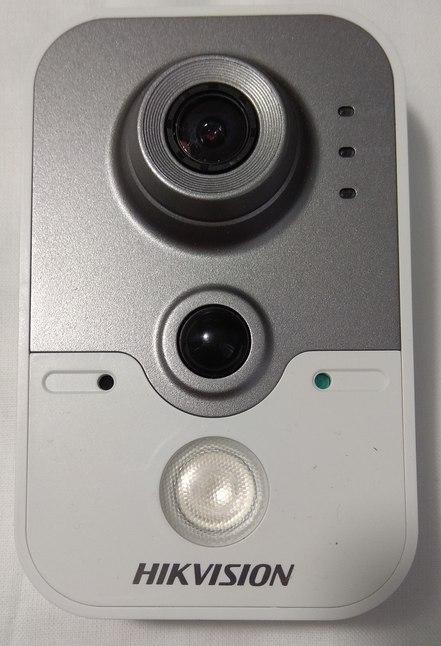
In this article, I would like to share a quite detailed instruction to restore the functionality (sometimes it is called as “unbricking”) of the budget network video camera Hikvision DS-2CD2420F-I (Fig. 1). This instruction might be applied to the other series of IP-surveillance cameras Hikvision or help to restore firmware of similar devices. The reason for preparing the article is the lack of information on the unordinary situation of replacing or updating the device firmware (e.g. resetting the forgotten password) with using the TFTP server, when the camera cannot be detected by the network scanner SADP (the software from the manufacturer) and connected to the TFTP server during the boot-up.
 |
|
| Figure 1. | IP- video camera Hikvision DS-2CD2420F-I. |
I happened to get two new IP-video cameras Hikvision DS-2CD2420F-I, which were not detected in the IP local network as well as by the network scanner SADP (the utility is available to download on the Hikvision Company’s website). Even their MAC-addresses were not detected in the local network. The network video camera belongs to the series DS-2CD2X22F-IS, platform R2, matrix 2 MP (this information as well as the relevant firmware can be found on the manufacturer’s official website). The attempts of applying standard IP-addresses were unsuccessful. The actions according to the instructions on replacing/updating firmware via the TFTP server offered on various sites were unsuccessful either – it was impossible to connect the cameras to the TFTP server.
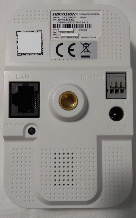
The video camera was also reset to the factory settings by pressing the button “WPS/RST” on the back of the camera (Fig. 2); when the camera power is off, press and hold the button “WPS/RST” for 15 seconds, then holding the button “WPS/RST” pressed, turn on the power and hold the button pressed for another 15 seconds. However, no external manifestations of the successful reset will be seen. After resetting, the cameras were still not detected on the local network and could not be connected to the TFTP server.
 |
|
| Figure 2. | Rear view of IP-video camera DS-2CD2420F-I with the ports and button WPS/RST. |
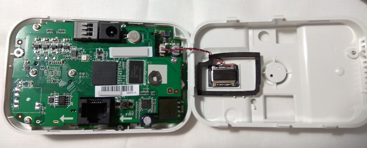
The video camera was decided to disassemble in order to inspect the printed circuit board visually and check the supply voltage. The case is assembled with plastic latches on perimeter and one screw under the sticker (Fig. 3).
 |
|
| Figure 3. | IP-video camera DS-2CD2420F-I without a case back. |
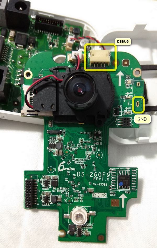
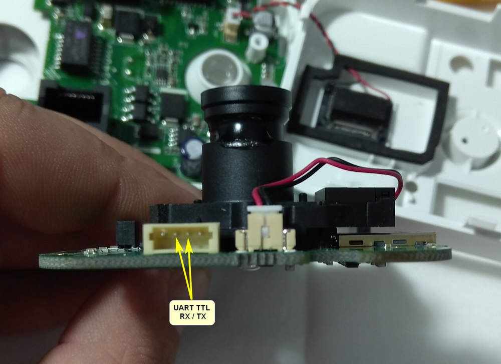
The visual inspecting and checking of the supply voltage did not reveal any malfunctions. However, after dissembling the upper printed circuit board with the matrix and the optical system in the upper part near the lens, a 4-pin port (Fig. 4) was noticed. It could be a debugging interface UART, with which, at least, the device’s boot progress can be seen and its functionality can be evaluated.
 |
|
| Figure 4. | The location of the debugging port connector on the circuit board of IP-video camera DS-2CD2420F-I. |
With using a multimeter and a microscope, the edge connector pins were figured to be the power +3.3 V and “grounding” (GND), and the two middle pins go directly to the processor. Therefore, the signal lines (Rx/Tx) of the adapter USB-UART should be connected to the two middle connector pins, and the common (GND) should be connected to the common point on the circuit board (Fig. 4, 5). If the output of the debugging information in the terminal program is not seen, just swap the signals.
 |
|
| Figure 5. | The location of the signal pins (Rx/Tx) in the debugging interface connector. |
Connect the adapter USB-UART to the computer. Next, download and install the terminal program; I use PuTTY. In the program settings, select the serial port (Serial), indicate the port number (Serial Line) related to the adapter USB-UART, indicate the exchange speed (Speed) 115200 and press the button “Open”.
After opening the terminal window, supply power (12V) to the camera and, if everything is done correctly, in the window we can see the output of debugging information about the download progress. If otherwise, it is necessary to check the port parameters and the connection of the Rx/Tx signal lines of the adapter USB-UART to the debugging interface (swap them).
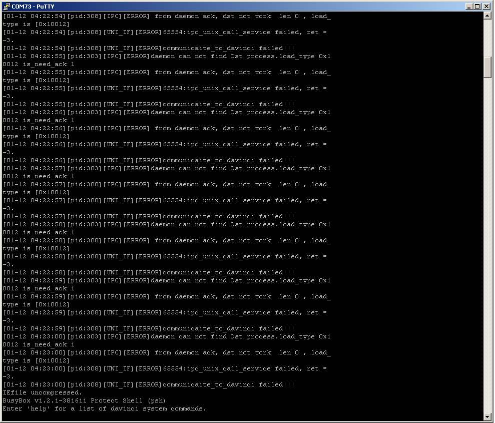
In my case with the two new cameras for debugging information, I realized that at some stage of downloading, the errors appear and the download stops (Fig. 6).
 |
|
| Figure 6. | Error messages while booting the operating system of the video camera DS-2CD2420F-I. |
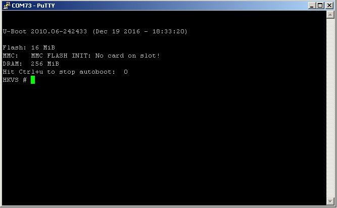
Now, let us try to replace/update the video camera firmware. To do this, it is necessary to start the boot process again (switch off and on the power of the camera). When the boot loader starts (U-Boot), interrupt the download by pressing Ctrl+U in the terminal. The invitation for work (a command line) “HKVS #” will appear (Fig. 7).
 |
|
| Figure 7. | Stop the autoboot with pressing Ctrl+U. |
Enter help command and get a list of all the available commands in the bootloader (Fig. 8).
| Figure 8. | The result of the "help" command in the U-Boot bootloader. |
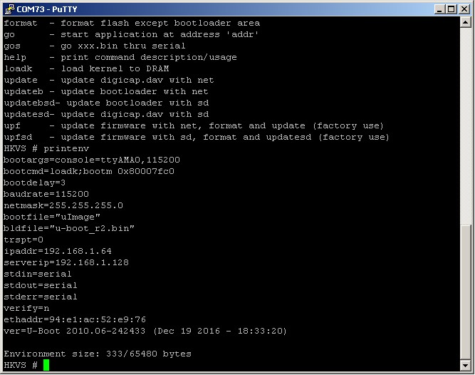
Now, it is necessary to see (and, if necessary, to change) the parameters of the boot loader environment. To do this, enter the command printenv (Fig. 9).
 |
|
| Figure 9. | The result of the “printenv” command in the U-Boot bootloader. |
We are interested in two parameters: ipaddr and serverip. The parameter serverip indicates the TFTP server address to which the video camera will send a request to replace/update the firmware at startup,and as we see, it should be 192.168.1.128. It is worth mentioning that all the net sources on firmware flashing IP video cameras Hikvision indicate that the TFTP server should be started at address 192.168.0.128 (in the network connection settings). The parameter ipaddr is the IP address of the camera (for the bootloader environment).
Thus, to update the firmware, it is necessary to start the TFTP server (with the firmware file) at address 192.168.1.128 and restart the camera, so that the bootloader automatically boots and updates the firmware. Alternatively, the parameters serverip and ipaddr can be changed in accordance with the local network configuration to which the video camera and the computer with the TFTP server are connected. In this case, the camera was connected directly to the computer, so we need to configure IP settings in network protocol version 4 (Network Protocol Version 4 (TCP/IPv4) Properties window). Set "Use the following IP adress": IP adress 192.168.1.128, Subnet mask 255.255.255.0, Default gateway 192.168.1.64. Click "Ok" button.
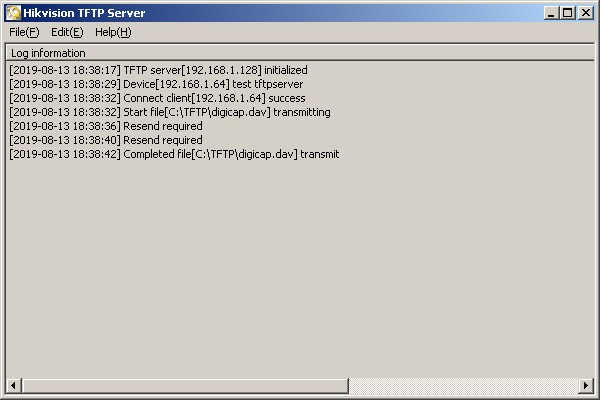
After that, start the TFTP server (the firmware file digicap.dav should be in the folder with the TFTP server program). The server should be initialized at address 192.168.1.128 (Fig. 10). Next, in the terminal program, enter the command “reset” for resetting the camera and observe the camera be connected to the TFTP server and successfully load the firmware into memory. Then, the TFTP server should be closed so that the video camera cannot be connected to the TFTP server for updating, after previous updating and subsequent resetting. Resetting the camera should be carried out from the command line, because when switching the power off and on (for resetting), the camera could not be connected to the TFTP server.
 |
|
| Figure 10. | The TFTP server program window displays the server address, active connections and file transfer steps. |
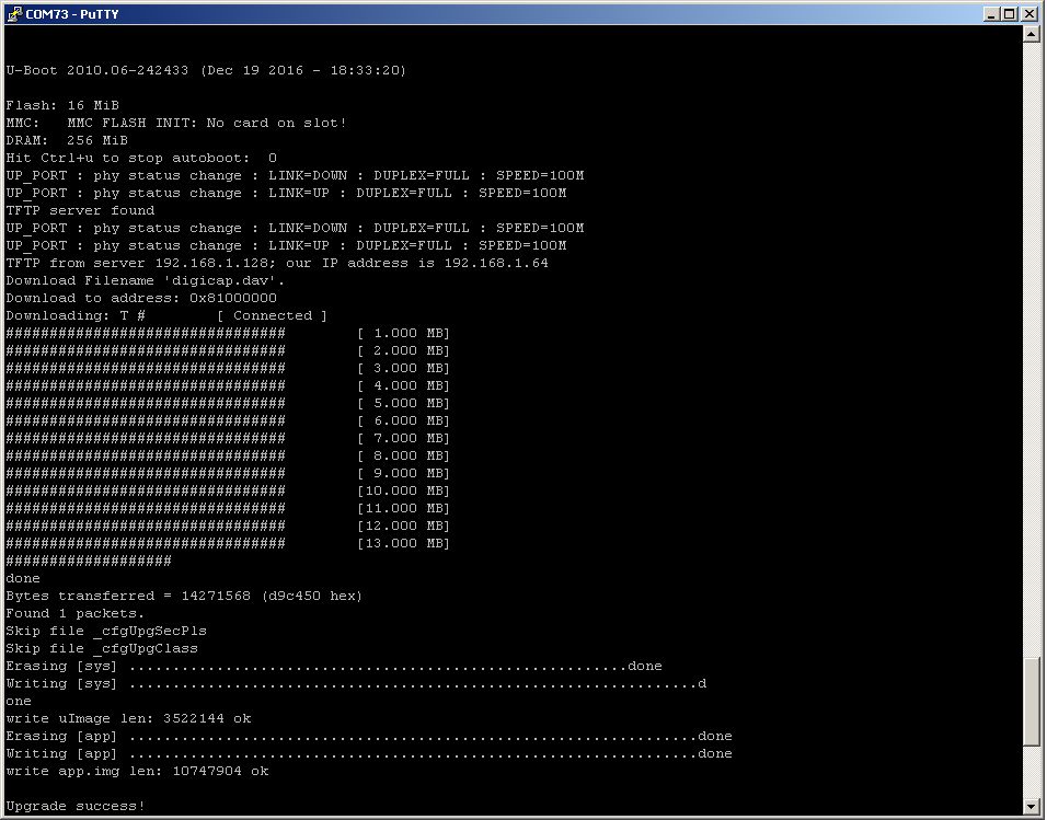
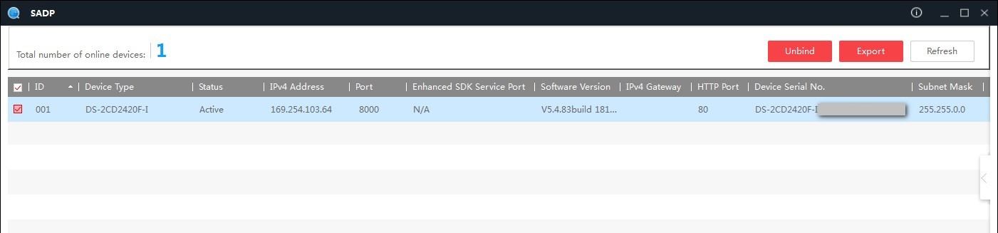
In the terminal program, the downloading progress of the file and updating of the firmware can also be seen. If everything has passed successfully, at the end of the process the message “Upgrade success!” will appear (Fig. 11). After that, the camera will be reseted automatically, and in 2-3 minutes, it will be detected in the program of the network scanner SADP (Fig. 12).
 |
|
| Figure 11. | The process of downloading the firmware file and updating it. |
 |
|
| Figure 12. | After replacing/updating the firmware, the video camera DS-2CD2420F-I is detected in the network scanner SADP. |
Now the camera needs to be activated (It's about my new cameras) and you can start with further configuration and use.
References
- PuTTY Software
- Hikvision Firmware
- Hikvision Software Tools
- Hikvision DS-2CD2420F-I IP camera. Documents
Downloads
- TFTPServer Software