What is Air Pollution?
Air pollution is the presence of excessive amount of unwanted & harmful solid and gases substances in the air.
Cause and Effect of Air Pollution
Recently, many cities in the world have encountered rapid urbanization and this has prompted expanded air pollution level. Air pollution is recognized as one of the main detriments to human health. Climate change is one of the most serious issue caused by the air pollution.
How to Monitor the Air Pollution?
Air pollution is usually measure as Air Quality Index (AQI) in ppm, which is basically an index for measuring air pollution and various pollutants like PM 2.5, NO2, O3, CO, etc. Now a days due to growth of electronics components and availability of various sensors to measure the air pollutant different system is developed to monitor the amount of air pollutant in the air. In this article I will provide the details about Air Pollution Monitoring and Alter System using Arduino.
Required Components:
- Arduino Uno
- MQ-135
- Potentiometer (1K ohm)
- 16 × 2 LCD
- LED
- Buzzer
- 220 ohm resistor
- 1 K ohm resistor
- Breadboard
- Transistor BC547 / BC337
- Connecting wires
You can buy the components from https://utsource.net.
Interfacing of Components:
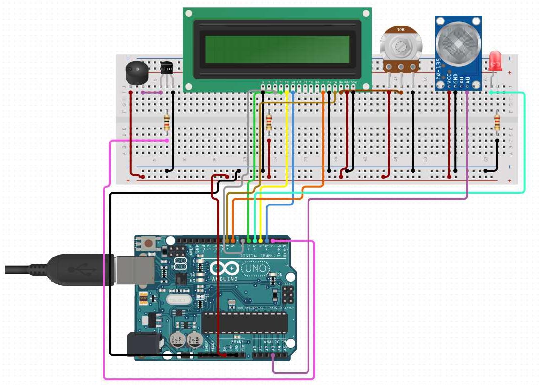
The best way to interface this circuit is to start with Arduino Uno board and LCD with breadboard. First place LCD on breadboard as shown in figure.
LCD to Arduino:
- D4 – Digital pin 3
- D5 – Digital pin 4
- D6 – Digital pin 5
- D7 – Digital pin 6
- E – Digital pin 8
- RS – Digital pin 9
Now connect A to 220 ohm resistor to +5V and K to ground. Finally connect the VO to middle pin of potentiometer and VDD to +5V, VSS & RW to ground. Also provide +5V (brown wire) and Ground (black wire) to potentiometer as depicted in figure.
Okay, now it is very easy to interface other components. Connect MQ-135 A0 pin to A3 pin of Arduino and connect VCC to +5V and GND to Ground. Connect Anode (+) of LED to digital pin 5 Arduino and Cathode (-) to 220 ohm resistor to Ground. Then, connect buzzer’s positive terminal to +5V and negative terminal to collector of transistor and from base of transistor connect 1 K ohm resistor to digital pin 2 of Arduino, in the end connect emitter to ground.
Working:
Arduino Uno is the main heart of this project and I have used MQ-135 Air Quality measurement sensor to measure AQI in ppm. So, first MQ-135 sensor will measure the amount of air pollutant in the air and provide the analog output to the A3 pin of the Arduino. Now, Arduino will send instructions to LCD for displaying the value of air quality provided by the MQ-135. Furthermore, to provide the alert to the user, I have set the threshold of 250 ppm in the code. So if measured AQI is more than 250 ppm then led will blink and buzzer will beep to alert the user about air quality.
Code:
I have use Arduino IDE to program Arduino Uno board from https://utsource.net. So, first in the code we need to include the LiquidCrystal.h library header file.
#include  LiquidCrystal.h
 //Header file for LCD
Define the variables for different pins used in Arduino board for LCD, Buzzer, LED and MQ-135. Also, set threshold value as 250 ppm.
const int rs = 9, en = 8, d4 = 3, d5 = 4, d6 = 5, d7 = 6; //pins of LCD connected to Arduino.
LiquidCrystal lcd(rs, en, d4, d5, d6, d7); //lcd function from LiquidCrystal
int buz = 2; //buzzer connected to pin 2
int led = 5; //led connected to pin 5
const int aqsensor = A3; //output of mq135 connected to A3 pin of Arduino
int threshold = 250; //Threshold level for Air Quality
This will run one time and here we need to set Buzzer, LED as output device and MQ-135 as input device to Arduino Uno. Serial UART and LCD is also initialized.
void setup()
{
pinMode(buz, OUTPUT); // buzzer is connected as Output from Arduino
pinMode(led, OUTPUT); // led is connected as output from Arduino
pinMode(aqsensor, INPUT); // MQ135 is connected as INPUT to Arduino
Serial.begin(9600); // begin serial communication with baud rate of 9600
lcd.clear(); // clear lcd
lcd.begin(16, 2); // consider 16,2 lcd
}
This will run infinite times and here we write our logic to read MQ-135 sensor data and display it on LCD screen and condition to turn ON and OFF LED and Buzzer.
void loop()
{
int ppm = analogRead(aqsensor); // read MQ135 analog outputs at A0 and store it in ppm
Serial.print("Air Quality: "); // print message in serail monitor
Serial.println(ppm); // print value of ppm in serial monitor
lcd.setCursor(0, 0); // set cursor of lcd to 1st row and 1st column
lcd.print("Air Qualit: "); // print message on lcd
lcd.print(ppm); // print value of MQ135
if (ppm > threshold) // check is ppm is greater than threshold or not
{
lcd.setCursor(1, 1); // jump here if ppm is greater than threshold
lcd.print("AQ Level HIGH");
Serial.println("AQ Level HIGH");
tone(led, 1000, 200); // blink led with turn on time 1000mS, turn off time 200mS
digitalWrite(buz, HIGH); // Turn ON Buzzer
}
else
{
digitalWrite(led, LOW); // jump here if ppm is not greater than threshold and turn off LED
digitalWrite(buz, LOW); // Turn off Buzzer
lcd.setCursor(1, 1);
lcd.print("AQ Level Good");
Serial.println("AQ Level Good");
}
delay(500);
}
The article is provided by Utsource