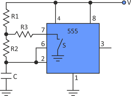
A free-running generator built on the standard configuration of the 555 timer can't provide a duty cycle of exactly 50%. That's a well-known fact. Fortunately, there are several ways to get around this problem. The best is to place an extra resistor, R3, between the two regular resistors, R1 and R2, and the chip's discharge pin (Fig. 1).
 |
|
| Figure 1. | Adding R3 to a standard 555 timer circuit allows a designer to create a 50% duty cycle. |
The problem is that variations in R3 strongly affect output frequency [1]. This idea shows how to achieve an adjustable 50% duty cycle with minimum frequency change.
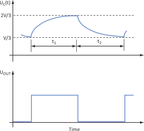
Even with the extra resistor, the timer operates in its usual way. When switch S inside the chip is open, capacitor C is charged through the R1-R2 network (Fig. 2), and the capacitor's voltage rises. When it reaches 2/3 of the power supply, V, the switch closes and capacitor starts discharging. When the voltage drops to the V/3, the switch opens again and the cycle repeats.
 |
|
| Figure 2. | The third resistor doesn’t affect the circuit’s normal charge-discharge cycle. |
The time intervals t1 and t2 are:
 |
(1) |
 |
(2) |
where p = R2/R1 and q = R3/R1. For a 50% duty cycle, t1 = t2, so:
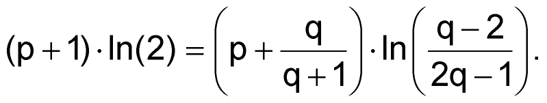 |
(3) |
And frequency is simply:
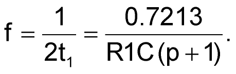 |
(4) |
Equation 3 is a relation between p and q. If p is set, then q can be calculated. Note that the term under the log operator at the right side must always be positive. This is fulfilled when both the nominator and denominator have identical signs, and it leads to two intervals for q, one from 0 to 0.5 and the other from 2 to infinity. This said, a simple iterative procedure can be used to calculate q. When that's done, R1, R2, and R3 can be defined.
The procedure is as follows:
- Set the desired frequency and select a value for C.
- Select the value of p and calculate q from Equation 3.
- Calculate R1 from Equation 4.
- Calculate R2 = pR1.
- Calculate R3 = qR1.
Table 1 shows the nominal values of R1n, R2n, and R3n determined with this procedure for five values of p, with a frequency of 20 kHz and C of 1 nF.
| Table 1. | R1, R2, and R3 versus p | ||||||||||||||||||||||||||||||
|
|||||||||||||||||||||||||||||||
Since the resistors must be rounded to standard values, the duty cycle will not be exactly 50%. The question is how to adjust it with minimum change of frequency. The answer is clear from Table 2, where percentage deviations of the duty cycle, DC, and frequency, F, are calculated when one of the three resistors is increased by 5%, while the other two are kept constant. Note that the best results are obtained when R1 is used to adjust the duty cycle.
| Table 2. | Duty cycle (DC) and frequency (F) deviations with changing resistances |
||||||||||||||||||||||||||||||||||||||||||
|
|||||||||||||||||||||||||||||||||||||||||||
A circuit designed according to the described procedure (with p = 1) was tested. Resistor values were: R1 = 18.2 kΩ, R2 = 18.2 kΩ, and R3 = 4.12 kΩ. Then R1 was modified to be able to change by ±5%. All resistors are of 1% tolerance. Table 3 shows that the results, particularly the duty cycle, were very close to the predictions in Table 2. They're also much better than what is reported in the above reference [1], where R3 is the variable resistor.
| Table 3. | Results from test circuit | ||||||||||||||||||||
|
|||||||||||||||||||||
The differences between theory and experiment are caused by resistor tolerances. Obviously, frequency suffers more from them. If tighter frequency control is required, a larger value of p can be selected and/or more precise resistors can be used. The first approach affects duty cycle adjustment span; the second affects the price. If needed, frequency can be adjusted independently of the duty cycle by varying capacitor C.