Many applications, such as medical therapies, magnetic stirrers, and induction heating, call for a rotating magnetic field, which you can generate by attaching multiple permanent magnets to a dc motor. This technique involves problems, including noise and the need to maintain the moving parts. This Design Idea describes how you can instead use a microcontroller and a full-bridge driver to generate variable magnetic fields without mechanical elements. The approach requires no maintenance, does not wear out, and provides high-precision speed control. It does, however, require large cores to achieve powerful magnetic excitation.
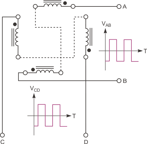
You can excite a stationary magnetic coil with an ac current, which induces a north pole and a south pole that change at the frequency of the signal excitation. You can increase the number of poles by implementing a configuration with more magnetic coils. Figure 1 shows a practical arrangement of the coils and the typical excitation waveforms. Note that the terminals of each pair of coils connect in series opposition to always obtain magnetic fields with different polarity.
 |
|
| Figure 1. | Two pairs of magnetic coils and their excitation waveforms show how to generate a rotating magnetic field. |
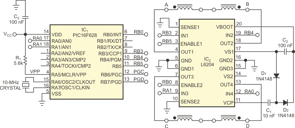
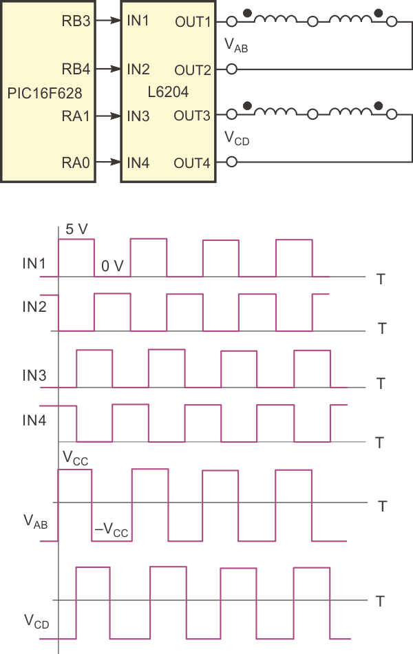
Multiple ICs can drive inductive loads. This circuit uses an L6204 dual full-bridge driver. Each bridge has four power-DMOS transistors with on-resistances of 1.2 Ω. A PIC16F628 microcontroller controls the switches of the dual-bridge driver (Figure 2). Typical waveforms show how each circuit is excited (Figure 3).
 |
|
| Figure 2. | The circuit comprises a full-bridge driver and a microcontroller. |
To ensure the correct driving of high-side drivers, the circuit supplies a voltage higher than the supply voltage at IC2’s Pin 20. External capacitors C1 and C2 and diodes D1 and D2 use a charge-pump method to produce this voltage. You can independently control the four half-bridges by means of the IN1, IN2, IN3, IN4, ENABLE1, and ENABLE2 inputs.
 |
|
| Figure 3. | Waveforms show how each coil is excited. |
The microcontroller timer's interrupt generates the IN1 to IN4 waveforms with high precision. Using a 10-MHz oscillator crystal and fixing the postscaler to eight, the microcontroller's counter increments every 3.2 µsec: 1/((10 MHz/four instructions)/eight). Taking into account that the interruptions generate when the counter overflows and the maximum count is as high as 65,535, or 16 bits, you can program the interruptions at 3.2 µsec and 210 msec: 3.2×65,535.
From this wide range of interruptions, the firmware lets the user select the precharge within a small subrange of frequencies divided into 10 levels, meaning that you must vary the interruption from 49.89 to 60.45 µsec, a good range for this application. The new frequency of the interruption has a simple calculation that includes the level; the maximum frequency; and the separation between levels, which is a constant value that the operations include.