Alan Stummer
Fans can be necessary for circuit cooling, but continually running a fan at a rated voltage will cause mechanical failure, usually in the bushings or bearings. By running it only when and as fast as needed, you can greatly extend its useful life as well as the life of the equipment it is cooling.
A simple on/off fan control will work, but it can cause switching transients and similar problems as the fan cycles. A proportional controller that starts the fan when circuit temperature passes a threshold, speeds up the fan as the temperature rises, and slows down and stops the fan when the circuit cools down is more elegant.
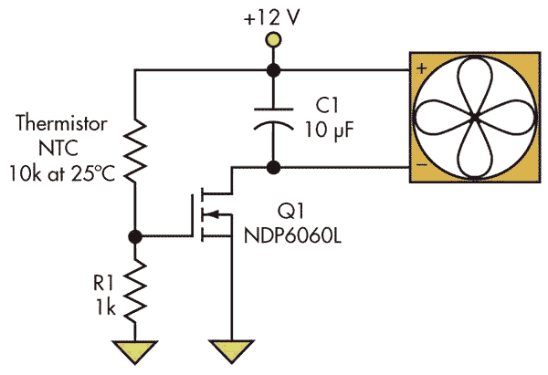
Most proportional fan speed controllers are far fancier than required, though, because circuit cooling isn’t really a precise science. This simple circuit is just as effective as a fancy design and has been used many times with great success (Fig. 1). It requires only a thermistor for temperature sensing, a FET to control the fan, one pull-down resistor, and a bypass capacitor to keep the purists happy. It assumes the thermistor is the more common negative temperature coefficient (NTC) type. If you wish to use a positive temperature coefficient (PTC), then reverse the thermistor and pull-up resistor.
 |
|
|
Figure 1. |
A thermistor and FET provide a bare-bones proportional controller for a dc cooling fan. |
At room temperatures, the FET gate voltage is below its typical threshold value Vgs(th), so the drain current is zero and the fan is off. As the temperature rises, the thermistor’s resistance drops, causing the gate voltage to rise above Vgs(th), and the FET begins to conduct. At still higher temperatures, the FET saturates and the fan runs at full speed. In practice, the temperature has to increase approximately 5°C for the fan to go from off to fully on.
The pull-down resistor R1 determines the threshold temperature at which the fan starts running. For example, ON Semiconductor’s NTD4959NH FET in a D-Pak package has a gate threshold of 2.0 ±0.5 V. Panasonic’s ERTJ1VR103H thermistor is in a 0603 (metric 1608) surface-mount (SMT) package and is nominally 10 kΩ at 25°C. To set the threshold temperature at 40°C, with a +12-V bias from the fan supply, the resistor would be:
R1 = RThermistor × Vgs(th)/(12 V – Vgs(th))
Using 2.0 V as the typical value of Vgs(th) and (from the data sheet) RThermistor at 40°C = 5.067 kΩ, you get R1 = 1.00 kΩ to the nearest standard 1% value.
With a fixed resistor, there will be some production variations in the actual threshold temperature because of variability in Vgs(th). For low production volumes, you could replace the resistor with a trimming potentiometer to allow adjustment of the threshold temperature. But for lowest cost, you may have to simply tolerate the variations.
Serendipitously, N-channel MOSFETs have gate thresholds with a negative temperature coefficient, which will help to mitigate the effects of Vgs(th) variability. Still, to ensure this circuit will work, you need to check that the temperature threshold range is acceptable in your system.
Working backwards with the extreme upper and lower values for Vgs(th) from the datasheet provides the worst case temperature thresholds:
Vgs(th)min = 1.5 V and R1 = 1.00 kΩ
So, the fan starts when:
RThermistor = 1.00 kΩ × (12 V – 1.5 V)/1.5 V = 7.00 kΩ
which occurs at a temperature of 33°C according to the datasheet. Similarly, the highest threshold temperature would occur when the thermistor is 3.80 kΩ at 46°C. Because most MOSFETs will have gate thresholds in the middle of the datasheet range, a production threshold temperature of 40°C ±3°C is a reasonable expectation.
A few things to consider: First, this design applies only to dc “muffin” type fans. It would be inefficient for large fans or arrays of fans and could not work for ac fans. Further, it requires fans that can automatically restart their movement. Most fans can, but be sure to verify with the datasheet. If your design requires the fan to be always running at some minimum speed, bypass the FET's drain to source with a resistor.
Also, realize that the FET may dissipate a significant amount of power when it is when operating in its linear region where the fan is not at full speed. Because this occurs when the fan is running, however, placing the FET in the fan’s airflow handily solves the problem.