Bernhard Linke
A single IC produces a code that indicates which button is pressed.
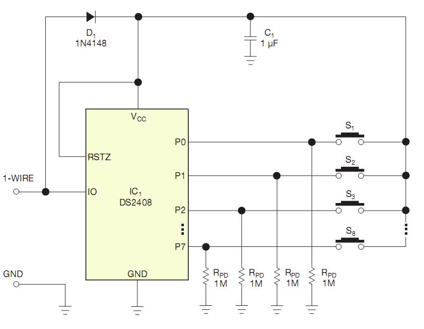
Sense multiple pushbuttons using only two wires figure 1Keyboards and numeric keypads often provide the user interface for electronic equipment, but many applications require only a few pushbuttons. For those applications, you can monitor multiple pushbuttons over a single pair of wires (Figure 1).
The multichannel 1-Wire addressable switch DS2408, IC1, provides PIO (input/output ports) P0 through P7, which in this application serve as inputs. The 1-MΩ RPD resistors connect these ports to ground to ensure a defined logic-zero state. Diode/capacitor combination D1/ C1 forms a local power supply that steals energy from the 1-Wire communication line. Pressing a pushbutton connects the corresponding port to the local supply voltage, which is equivalent to logic one. This change of state sets the port’s activity latch (Reference 1).
As a 1-Wire slave device, IC1 doesn’t initiate communications. Instead, the master device—typically, a microcontroller—polls the 1-Wire line. To minimize overhead, IC1 supports conditional search, a 1-Wire network function. Before using that function, however, you must configure IC1 according to the needs of the application. That configuration includes channel selection, which defines the qualifying input ports; channel-polarity selection, which specifies the polarity of the qualifying ports; choosing a pin or an activity latch for the port; and specifying whether the device will respond to activity at a single port, an OR, or at all ports, an AND.
Consider, for example, that IC1 shall respond to a conditional search if it detects activity at any of the eight ports. This search requires a channel-selection mask of 11111111b for address 008Bh. The numeral one indicates that IC1 has selected a port. This search also requires a channel-polarity selection of 11111111b for address 008Ch, where the numeral one indicates a high level, and a control/ status register setting of 00000001b for address 008Dh, which selects the port’s activity latch as a source and specifies OR as the conditional search term—that is, activity at any port.
After power-up, the configuration data must be loaded into IC1 using the write-conditional-search-register command. Next, the channel-access-write command, with FFh as a PIO output-data byte, defines the ports as inputs. Subsequently, the issue of a reset-activity-latches command completes the configuration. IC1 is now ready to handle pushbutton activity.
After you configure IC1, the application software enters an endless loop, in which a conditional-search command follows a 1-Wire reset. With no pushbutton activity, IC1 does not respond, as a logic one indicates, for the 2 bits immediately after the conditional-search-command code. In that case, the microcontroller cancels the conditional search and starts over.
If IC1 responds to the conditional search, the first 2 bits will be one and zero, representing the least-significant bit of the device’s family code, 29h, in its true and inverted forms. In that case, the microcontroller should complete the conditional-search flow, which comprises a 192-bit sequence. Next, the microcontroller reads from IC1 by issuing a read-PIO-registers command using 008Ah, the address of the PIO-activity-latch-state register. The microcontroller then issues a 1-Wire reset, a resume command, and a resume-and-reset-activity-latches command. It then returns to the endless loop, polling for the next pushbutton event.
If IC1 responds and no other 1-Wire slave is connected, the microcontroller could cancel the conditional search after reading the first 2 bits, issue a 1-Wire reset, issue a skip-ROM command, and then read the PIO-activity-latch-state register. Next, it must issue a 1-Wire reset, a skip-ROM command, and a reset-activity-latches command before returning to the endless loop.
The code read from the PIO-activity-latch-state register tells which button was pressed. If you press S1, the data is 00000001b; if you press S2, it is 00000010b; and so forth. At least one of the 8 bits will be one. If you press several buttons after the last reset-activity-latches command, several bits are one. The application software must then decide whether such a condition is valid. In the simplest case, one-of-eight code, the software considers all codes that have several bits at one as invalid.
Sense multiple pushbuttons using only two wires figure 2You can expand this concept to more than eight pushbuttons. Instead of associating one pushbutton with one port, you can associate additional pushbuttons with two simultaneously activated ports, representing two-of-eight code (Figure 2).
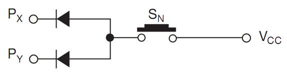
If another pushbutton activates PX or PY, the diodes prevent that activity from propagating to other ports. Again, the application software must check the code it reads from the PIO-activity-latch-state register to decide whether it is valid. The theoretical limit of this concept is 255 pushbuttons, which require combinations of two, three, four, five, six, seven, or eight diodes per additional pushbutton. When the cost of diodes for each additional pushbutton begins to exceed the benefits, you will find that adding another DS2408 is more cost-effective.