The project is intended for noncommercial usage only
Paweł Kisielewski
One of a kind, portable AVR programmer! Helps wherever you need to update the device firmware, where target device is in a hard-to-reach location and you can’t (or don’t want to) bring your laptop with a bunch of wires with you. Trivially easy to use, super cheap to make, super small, super fast, uses SD cards…
Features:
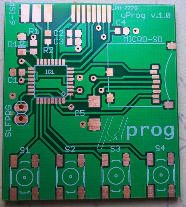
- super small – dimensions 44 x 39 x 5,5 mm
- super fast – write up to 12,5kB/s, read up to 14,5kB/s
- uses cheap storage medium – small MICRO SD cards
- supports FAT16 and FAT32 file systems
- can read, write, verify flash and eeprom memory
- can read, write, verify fusebits and lockbits
- write and read to BIN, HEX, and TXT files
- can set default values of fusebits, erase memories
- cheap, easy to obtain, LPH7779 graphic display
- shows funny animations after every operation
- standard programming header – Atmel 6-PIN ISP
- has a function of auto-update its own firmware (from SD)
- very simple to use, 4 buttons navigation
- user-setting menu
- programming speed auto-selection (up to 4MHz)
- Operates at 3V, programs chips supplied from 3V to 5V
Supported chips list:
Green – tested chips.
Note that yet not all chips are fully supported – see “chip.db” file. Incomplete entries means that only fusebits and lockbits operations are working.
- 1kB:
- AT90s1200, Attiny11, Attiny12, Attiny13/A, Attiny15
- 2kB:
- Attiny2313/A, Attiny24/A, Attiny26, Attiny261/A, Attiny28, AT90s2333, Attiny22, Attiny25, AT90s2313, AT90s2323, AT90s2343
- 4kB:
- Atmega48/A, Atmega48P/PA, Attiny461/A, Attiny43U, Attiny4313, Attiny44/A, Attiny48, AT90s4433, AT90s4414, AT90s4434, Attiny45
- 8kB:
- Atmega8515, Atmega8535, Atmega8/A, Atmega88/A, Atmega88P/PA, AT90pwm1, AT90pwm2, AT90pwm2B, AT90pwm3, AT90pwm3B, AT90pwm81, AT90usb82, Attiny84, Attiny85, Attiny861/A, Attiny87, Attiny88, AT90s8515, AT90s8535
- 16kB:
- Atmega16/A, Atmega16U2, Atmega16U4, Atmega16M1, Atmega161, Atmega162, Atmega163, Atmega164A, Atmega164P/PA, Atmega165A/P/PA, Atmega168/A, Atmega168P/PA, Atmega169A/PA, Attiny167, AT90pwm216, AT90pwm316, AT90usb162
- 32kB:
- Atmega32/A, Atmega32C1, Atmega323/A, Atmega32U2, Atmega32U4, Atmega32U6, Atmega32M1, Atmega324A, Atmega324P, Atmega324PA, Atmega325, Atmega3250, Atmega325A/PA, Atmega3250A/PA, Atmega328, Atmega328P, Atmega329, Atmega3290, Atmega329A/PA, Atmega3290A/PA, AT90can32
- 64kB:
- Atmega64/A, Atmega64C1, Atmega64M1, Atmega649, Atmega6490, Atmega649A/P, Atmega6490A/P, Atmega640, Atmega644/A, Atmega644P/PA, Atmega645, Atmega645A/P, Atmega6450, Atmega6450A/P, AT90usb646, AT90usb647, AT90can64
- 128kB:
- Atmega103, Atmega128/A, Atmega1280, Atmega1281, Atmega1284, Atmega1284P, AT90usb1286, AT90usb1287, AT90can128
- 256kB:
- Atmega2560, Atmega2561
Schematic Diagram
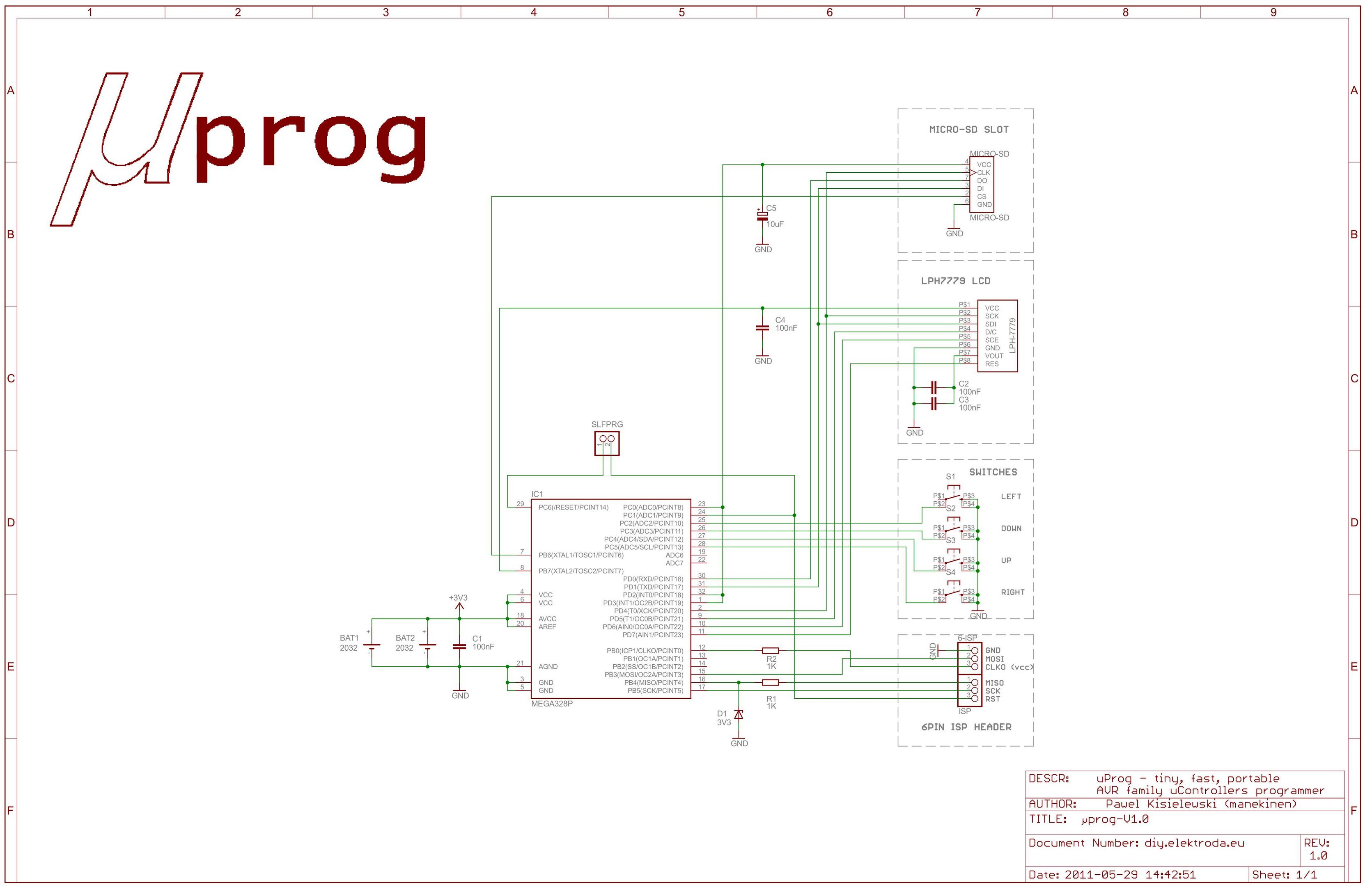
Internal Atmega328P oscillator can be calibrated in very wide range. Fabric calibrated to 8MHz can be “calibrated” by user from 50% even to 200%, i.e. from 4MHz even to 16MHz. Change bit4 to “1″ in “config.ini” file will chose the maximum available speed – this will significantly speed up programming process, but manufacturer don’t guarantee correct work in such conditions (supply voltage vs frequency). By default, this setting is disabled.
Display which i used is original (taken from 3310 cellphone) – it has a PCD8544 driver, 84×48 organization, standard set of instructions, and it can work with 4MHz signal – and it works good at 4MHz.
Display needs a proper capacitor for build-in voltage converter (C2, C3), nominal value is 1µF. Mine works very well with 200nF capacitance. If you experience problems with contrast, increase this capacitance – more capacitors can be soldered in place of C2 and C3 – just solder them vertically. If your LCD have a copper solder pads, you can easily solder him to PCB with wires. If it have a glass contact pads, use original rubber contact strip (zebra strip) which was in cellphone, lcd in that case must be well mounted. In my case, i used parts of “E+J connector” case. You can use just anything which internal dimension is 5,2mm.
Memory card, depending on what type we get, can take up to 100mA while init – this is a huge current for small battery. C4 capacitor helps to keep this voltage for initialization process, and will be good if this cap has high capacity, but not too high because it is charged from three µC pins, which we can’t damage. For me, 10µF capacitor is sufficient to start every SD card that i tested.
Supplying, voltages:
Device is designed to work with battery, but there is no problem to use proper power supply.
- Nominal operating voltage: 3,3V
- Maximal operating voltage: 3,6V
- Minimal operating voltage: 2,7V*
- Power consumption at start: up to 100mA*
- Power consumption while programming: up to 10mA*
- Power consumption in menu: 5mA
- Power consumption when off (power-down): 0.10µA
*depends on SD card
There is a place for two CR2032 battery holders on bottom site of the pcb – when using these batteries, operating voltage will be 3V, and current efficiency of these batteries will be insufficient to power up the target chip – voltage drop will kill programming process or will mess up data in memory card. Instead of soldering these holders, you can connect your own battery with higher current (i.e. from cellphone), but make sure to not exceed maximum operating voltage which is 3,6V.
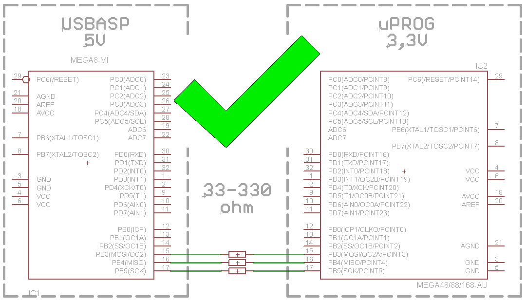
Programmer works with exactly that voltage which it gets from battery, because it does not have any voltage regulator on board. The whole programming process is also at this voltage (high state). Target chip can be programmed from 3V to 5V when programmer works with 3V. From one side, MI-SO input line is connected trough resistor and 3V3 zener diode to protect input line from voltages higher than VCC. From other side, target chip powered from 5V will recognize 3V at SCK and MO-SI lines as high state (see datashhet: electrical characteristics > dc characteristics > VIH = 0.6 VCC, this is 0.6×5V=3V – guaranteed value).
There is no mechanical switch, turning on and off is made by holding the LE button. After switching off, programmer will cut off power from display and memory card, and goes into deep sleep mode, taking only (typically) 0,1µA from battery.
39mm × 44mm × 5,5mm size PCB, doublesided. Vias pads are placed in easy accessible places (not under ic packages etc), so its easy to make it at home.
Before you burn flash! If you don’t have a programmer with signal voltage adjustment, please read this. The maximum input voltage that you can attach to the pin port is VCC+0.5V. So, if you supply this device from 3,3V and want to program it with standard 5V programmer – you will need to protect its ISP lines from damage.
Part 2. Usage, Function description, Speed tests
Downloads
Eagle 5.10 files: PCB, SCH; alternative PDF (PCB ver 1.0) - download
PCB and Schematic ver.1.1 - download
http://diy.elektroda.eu/uprog-maly-szybki-przenosny-programator-avr-z-sd/?lang=en