Testing of the board
Now the board is complete and ready for testing, which will be done in two steps. In the first step, we will test if the LCD, LEDs, and tact switches are properly wired on the board. We will connect them to PORTA and PORTB of PIC16F1827. The microcontroller will run at 500 KHz internal clock, so you can take the ceramic resonator out from its slot. You should use jumper wires to make the following connections.
- LCD: RS -> RA6, E -> RA7, D4 -> RA0, D5 -> RA1, D6 -> RA2, D7 -> RA7
- LEDs: Connect the eight LEDs to PORTB (RB0-RB7)
- Tact switches: Connect SW1 through SW6 to RB0-RB5 port pins
We will write a test program in mikroC Pro (mikroElektronika)for PIC that will first initialize the character LCD and send a test message to display. You can vary the contrast of the display through the LCD contrast potentiometer on the board. The PORTB is initially defined as output port and all the LEDs are turned on sequentially in forward and reverse direction. Next, the PORTB direction is changed to input to read the inputs from tact switches. All the six keys are tested by pressing them individually. The microcontroller sends a number between 1-6 to LCD for each key press. This completes the testing of the connections of the I/O components on the right side of the board.
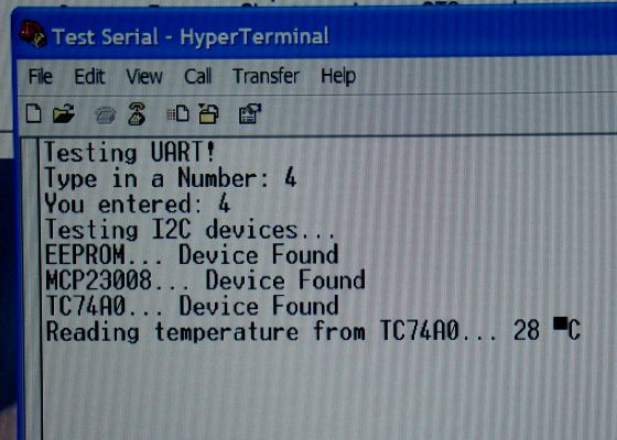
Next, we will test the UART port and I2C devices. The microcontroller will use an external 16.0 MHz resonator for its system clock. Connect the RB1 and RB2 pins to TTL Rx and Tx terminals of the UART module. The RS232 pins (Tx, Rx, and Gnd) must be connected to corresponding terminals of PC’s serial port. The Hyperterminal window on the PC will serve as the display module for this test. The board will send a message to the terminal window, “Enter a Number” and waits for a key to be pressed on the keyboard. When a key is pressed, the microcontroller will read it, and echo it back to the Hyperterminal window. Then, the microcontroller will test the presence of all I2C devices on the board. I2C communication will be implemented in software through RB4 and RB5 pins. So, connect RB4 and RB5 to SCL and SDA header pins, respectively. The PIC16F1827 will send the slave addresses of the three I2C devices sequentially. If the device acknowledges, the microcontroller will know about its presence. Then, the PIC16F1827 also reads the temperature value from TC74 sensor and displays it on the Hyperterminal window. This completes the second test.
Downloads
The source and HEX files for tests 1 and 2 - download