My 2010 Equinox has got every feature that a modern automobile should have. However, one thing that I personally find missing is the real-time monitoring of voltage across the car’s battery terminals. This may not seem to be that important but one of the most common reasons for a car battery failure is the faulty charging system. If the charging system is not working properly, the battery will not get the proper charging voltage (about 13.8 V for 12V battery) across its terminals and it could go flat. This project is about making a simple electronic voltage monitor system for car’s battery and its charging system. It plugs into the car’s cigarette lighter receptacle and displays the instantaneous output voltage across the battery terminals on a 4-digit seven segment LED display. This helps you to get early warnings for possible battery and its charging system problems. Microchip’s PIC16F1827 is the main controller in this project, which uses the built-in Fixed Reference Voltage (FVR) module to achieve a very precise and accurate A/D conversion of the battery voltage.
Theory
As I said this project is simply about making a precise digital voltmeter that plugs in to the car’s cigarette lighter receptacle and displays the instantaneous voltage across the battery terminals. When the engine is turned off, the voltage measured by this device is the actual output voltage from the battery. However, if the engine is on or the car is running, it actually measures the charging voltage across the battery that is coming from the car’s charging system (alternator + rectifier). The functional block diagram of this project is shown below.
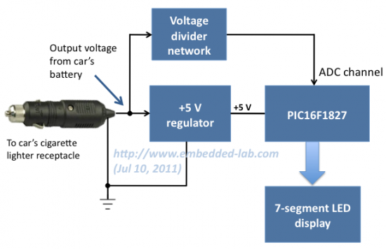
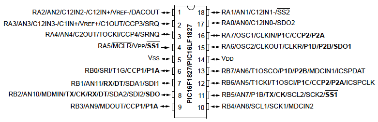
The +5V power supply for the PIC16F1827 microcontroller circuit is derived from the car’s battery output voltage (usually +12V) using a regulator IC (such as LM7805). The battery terminal voltage is measured through an ADC channel of PIC16F1827. The FVR module inside PIC16F1827 is chosen to derive a stable positive reference voltage of 4.096 V for precise A/D conversion. Before feeding to the ADC channel, the battery output voltage is scaled down to below the reference voltage by using a voltage divider network. The measured instantaneous battery voltage is shown on a 4-digit seven segment LED display.
Circuit diagram
The circuit diagram of this project is shown below. The PIC16F1827 microcontroller uses the AN4 ADC channel for measuring the voltage across the car’s battery terminals. The R1 and R2 resistors at the ADC input channel creates a simple voltage divider network to scale down the incoming voltage from the battery’s positive terminal. The maximum measurable input voltage at AN4 is 4.096 V (limited by using the internal 4.096 V reference voltage for A/D conversion). Therefore, the maximum input voltage (VBattery) that could be measured without A/D saturation can be obtained from the following equation,
4.096 V = R2*VBattery/(R1 + R2)
Or, VBattery = 16.93 V.
The range of input voltage can be increased simply by lowering the value of R2. The 5.1 V Zener diode is placed in parallel with R2 to prevent the voltage at the microcontroller’s ADC channel from going above 5.1 V. Otherwise, any accidental high input voltage could damage the microcontroller port permanently.
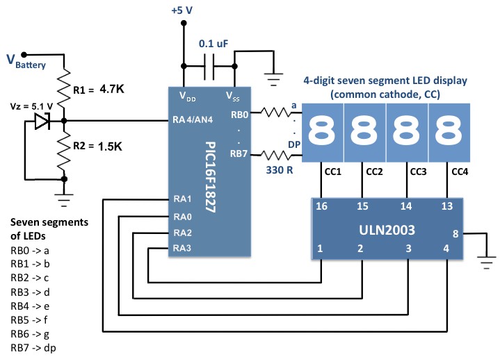
The measured voltage is shown on a 4-digit seven segment LED display (common cathode). The seven segments (a-g) and the decimal point (DP) are driven through PORTB of PIC16F1827. The microcontroller runs at 500 KHz using the internal clock source. The ULN2003 darlington array provides current sink to each of the common cathodes of the seven segment LED module.
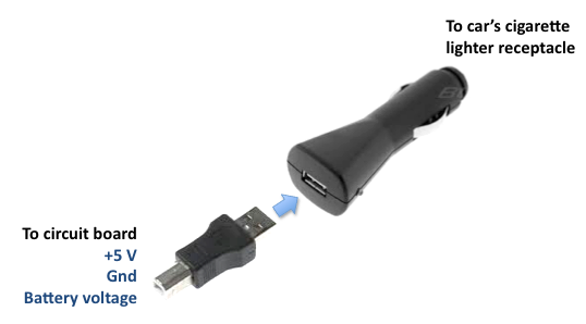
The regulated +5 V supply can be derived from the car’s cigarette lighter receptacle (12 V output) using LM7805 regulator IC. However, I preferred to use my spare USB car charger to serve this purpose.
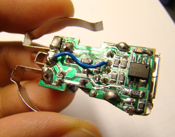
The USB port has 4 pins (+5 V, D+, D-, and Gnd). In the car charger, the D+ and D- pins are kind of useless. So I opened my USB car charger, disconnected the output D+ pin from rest of the circuit, and re-wired it to the input +12 V from the battery. Now, we have +5 V, Gnd, battery terminal voltage, and D- (useless) in the USB port pins of the car charger. Then I used an USB-A Male to B Male Adapter to connect these signal lines to the microcontroller circuit board.