In one of my previous posts, I discussed about Sensirion’s SHT11 and SHT75 sensors, which are capable of measuring both temperature and relative humidity. They are digital sensors and provide fully calibrated digital outputs for temperature and relative humidity. I also illustrated how to interface those sensors with a PIC microcontroller. Shawon Shahryiar from Dhaka, Bangladesh shared this project with us where he describes a method of interfacing the HSM-20G sensor to Atmel Atmega8 for measuring the ambient temperature and relative humidity. Unlike Sensirion’s SHT series, this is an analog sensor that converts the two ambient parameters into standard output voltages.
Shawon writes,
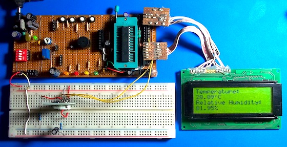
The materials used for the project are a ATMega8A micro, a HSM-20G analog relative humidity and temperature sensor module and my own-made 28 pin AVR development board along with some passive components. MikroC for AVR 5.00 compiler from mikroElektronika was used for coding.
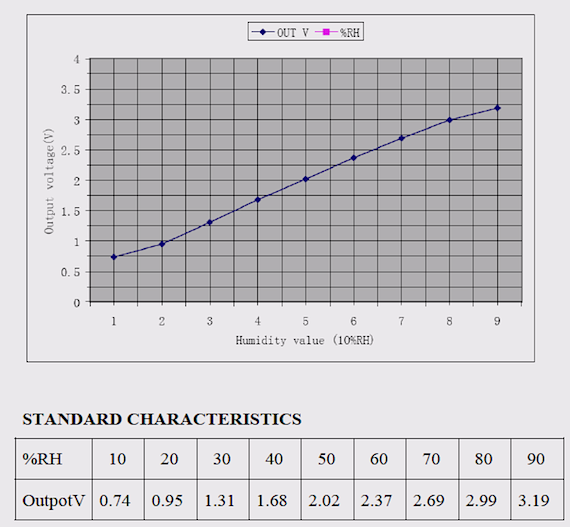
HSM-20G is an analog sensor module unlike SHT75 or SHT21. If you go through the datasheet of HSM-20G, you will find out that they have given output voltage data from the humidity sensor for certain relative humidity values and they have plotted a graph too. What I did is simply used those data to plot and check if their graph is valid or fake. Now as you may notice the plot is not linear but rather has curve-like nature. Thus I used MATLAB’s “polyfit” function to get a equation for the plotted curve to the third degree. The reasons for using a third degree equation are firstly AVR has a built-in hardware multiplier that works pretty fast and secondly I won’t be using the micro to do any other tasks rather than metering. This is enough for a fairly good precision. A second degree is not that good enough while a higher order equation is unnecessary. If you you go through my program, you will see the equation under the function “read_humidity()”. The micro computes the data it gets from the HSM-20G module for relative humidity and determines what it should show.
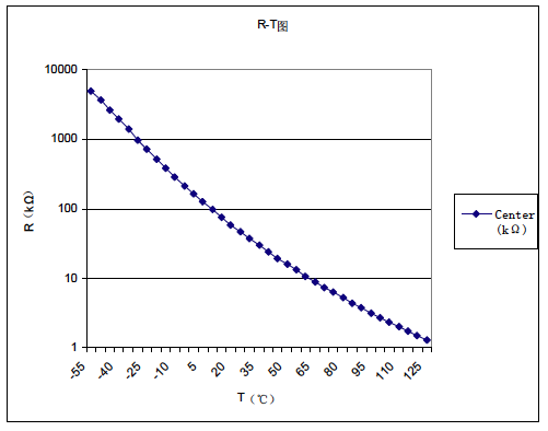
The same task I did for temperature measurement but finding its data was a little cumbersome. If you see the datasheet for the module, you will notice they have given a circuit for interfacing the module to other peripherals like a micro or a multimeter and I used that circuit. However since they don’t know what value of resistance the user will use at the temperature circuit side and because it’s a thermistor built inside rather than semiconductor type sensor, they have provided resistance values rather than output voltages at various temperatures. Therefore and since I used their circuit, I calculated the voltages at different temperatures from their data. Again I used the voltage and temperature data as I did for the relative humidity part.
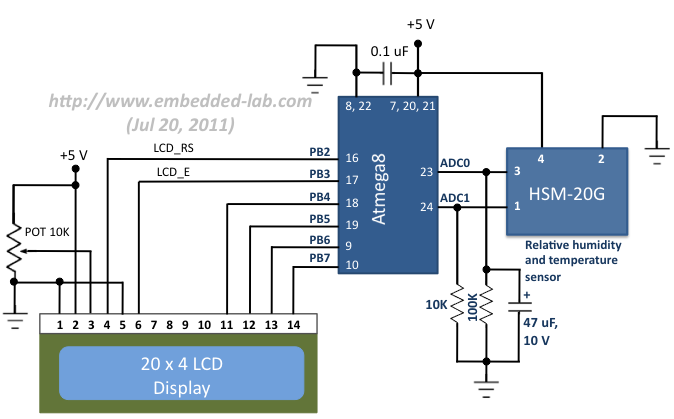
Circuit diagram
The circuit diagram is pretty simple. The two ADC channels (ADC0 and ADC1) of Atmega8 are used to measure the sensor output voltages that correspond to the ambient temperature and relative humidity. The two resistors and a capacitor connected to the output lines of the HSM-20G sensor are recommended in its datasheet. The results are displayed in a 4×20 character LCD.
Circuit diagram for interfacing HSM-20G to Atmega8