ChromationSystems
This Instructable covers creating a USB connected Human Interface Device Keyboard that has 10 button inputs which are mapped to key combinations in the firmware. Key combinations can be quickly accessed without using the keyboard which may be inconvenient to use. Such as with a MAME or similar machine where the keyboard may be stored or certain keys may be used frequently but aren't mapped to any of the arcade buttons.
Such as: Alt+F4 for Close Program, Windows+D to Show Desktop, Minimize Window, Maximize Window, Multiple Launch Program or Emulator, Alt+Ctrl+Del, Coin Buttons,
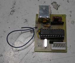
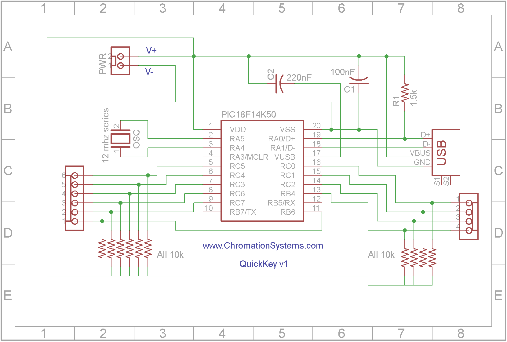
The custom hardware(circuit) is based on Microchip Solutions sample "USB Device HID Keyboard" firmware for the Low Pin Count USB Development Kit which uses a PIC18F14K50. The development kit is not required to recreate this as included here is a schematic, PCB layout and firmware to build one from scratch.
It does not require any external power supply, it draws from the USB host. All the keycodes are set in firmware and are for Windows based OS's, additional OSs could be used but the keycodes would have to be changed from firmware.
This device is similar to U-HID or similar but with a lot less keys and no software to change or set key combos.
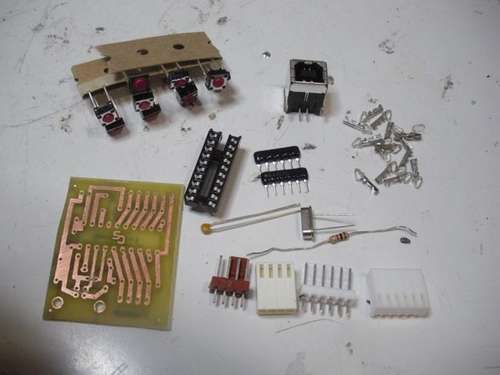
Parts:
- PIC18F14K50 - DIP package
- 2 × 10k 5 bused resistors
- USB Type B Socket
- 12 mhz Oscillator, series*
- 0.1uF disc Capacitor
- 220nF disc Capacitor
- 4 pin Header, such as Molex KK6410
- 4 pin Housing, such as Molex KK 6471
- 6 pin Header, such as Molex KK6410
- 6 pin Housing, such as Molex KK 6471
- Crimps, Molex KK 4809
- Wire, solid strand and stranded
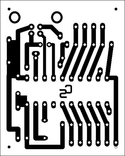
- Printed Circuit Board or Perforated Proto board and solid strand wire
- 10 Normally Open Push buttons, board mount
- USB Type B to Type A cable(most devices such as printers use them)
*Normal crystal oscillator can be used, just add a 22pF capacitor from each OSC pin to ground.
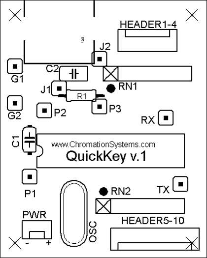
- Start with the 20-pin socket, the notch on the end marks the Pin 1 end. Carefully insert it, ensuring all pins line up.
- Resistor Buses are next, they each have 5 10k resistors in parallel within them with a common pin on one end, The common pin, which is marked with a dot on the SIP package should be lined up with the printed dot on the end of RN1 and RN2.
- Oscillator, ensure the solder joints are shiny and designing your own board, it should be as close to the MCU as possible.
- Capacitors C1 & C2: C1 is a 100nF disc cap for decoupling, C2 is a 220nF capacitor connected between the MCU's VBUS pin and V+.
- Resistor R1 pulls the Data+ line high, which signals to the Host what USB speed the Device runs at.
- USB Receptacle: It only goes in one way, Bend the mounting pins outward once it is in the board, solder all the contacts ensure their good joints. Make sure the solder doesn't bridge, as the contacts are quite close together.
- Headers: The polarized headers go in now, they can go in facing either way, there is a 4-pin and a 6-pin.
- PWR: Unused power header, leave it empty but solder over both pads. It is there in case more power than the bus can provide would be needed if the device was repurposed.
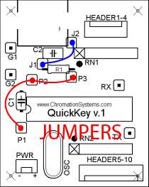
- Jumpers: Lastly the jumpers are installed, using these means that single sided copper circuit board can be used. Use some solid strand wire. And avoid other touching other parts, especially bare wire line on a capacitor.
- J1 is jumped to J2
- P1 is jumped to P2 which is jumped to P3. solder 2 wires into P2, then one wire each goes to P1 and P3.
- G1 and G2 are left open, explained in the next step.
- RX and TX are also left open and are not used, but are connected to the USART.
Buttons are connected as seen in the diagrams.
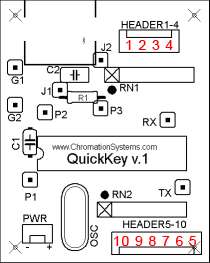
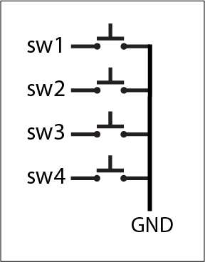
The buttons are pulled-high by the device, bringing an input pin to ground will signal that the button has been pressed. And send the firmware assigned command from the device to the host computer.