Pin mappings
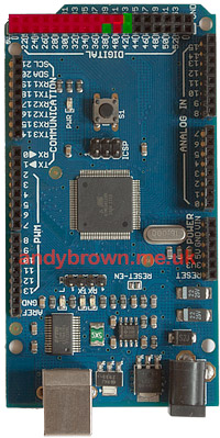
Here’s how the Arduino maps the xmem pins. As you can see they’re all conveniently placed in a block at the end of the board. That will make it easy for me to design a PCB that just plugs straight in. Thanks go out from me to the Arduino designers for thinking of this.
|
Arduino
|
AVR
|
SRAM
|
 |
|
22
|
AD0/PA0
|
D0
|
|
|
23
|
AD1/PA1
|
D1
|
|
|
24
|
AD2/PA2
|
D2
|
|
|
25
|
AD3/PA3
|
D3
|
|
|
26
|
AD4/PA4
|
D4
|
|
|
27
|
AD5/PA5
|
D5
|
|
|
28
|
AD6/PA6
|
D6
|
|
|
29
|
AD7/PA7
|
D7
|
|
|
30
|
A15/PC7
|
A15
|
|
|
31
|
A15/PC6
|
A14
|
|
|
32
|
A15/PC5
|
A13
|
|
|
33
|
A15/PC4
|
A12
|
|
|
34
|
A15/PC3
|
A11
|
|
|
35
|
A15/PC2
|
A10
|
|
|
36
|
A15/PC1
|
A9
|
|
|
37
|
A15/PC0
|
A8
|
|
|
38
|
PD7/T0
|
BANK0
|
|
|
39
|
ALE
|
latch enable
|
|
|
40
|
/RD/PG1
|
/RD
|
|
|
41
|
/WR/PG0
|
/WR
|
|
|
42
|
PL7
|
BANK1
|
|
|
43
|
PL6
|
BANK2
|
The pins overlaid in red are used by the xmem interface, those in green will be used by me to control the active memory bank.
Here’s the full schematic that I created using the free version of the Eagle PCB CAD design program.
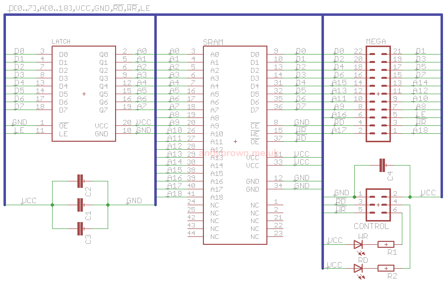
The schematic reflects the block diagram in the datasheet with the addition of 100nF capacitors around the power pins of the ICs and one 1µF across the board supply.
I have also added a LED each to the active-low /WR and /RD control lines so that reads and writes to the SRAM will be visible if enough happen in succession – a single read/write is so fast that the LED will not flash for long enough to be visible. These LEDs can be enabled with a jumper or disabled if I feel that I can’t afford the 7mA of current that they consume while active.
Part list
|
Part
|
Number
|
Package
|
Quantity
|
|
SRAM
|
Alliance AS7C4096A 12ns
|
44 pin TSOP-II
|
1
|
|
Latch
|
NXP 74AHC373
|
20 pin TSSOP-20
|
1
|
|
Capacitor
|
100nF
|
0603
|
3
|
|
Capacitor
|
1µF
|
0603
|
1
|
|
Resistor
|
approx 430Ω
|
0805
|
2
|
|
LED – yellow
|
Kingbright
|
1206
|
1
|
|
LED – red
|
Kingbright
|
1206
|
1
|
|
Jumper
|
2 pins
|
2.54mm
|
2
|
|
Male DIP header
|
22 pins
|
2.54mm
|
1
|
|
Male DIP header
|
6 pins
|
2.54mm
|
1
|
The PCB
I use the prototype PCB manufacturing service offered by ITead Studio. If your board is double sided and comes in at under 50mm square then they will charge US$9.95 for 10 copies including delivery.
Mine comes in at around 40×43mm so no problems there. ITead supply a DRC file that you can use to validate your design against their equipment. The finest trace/space they can handle is 6mil but in my opinion you’d be asking for manufacturing faults at that level so I try to stick to 10mil or higher.
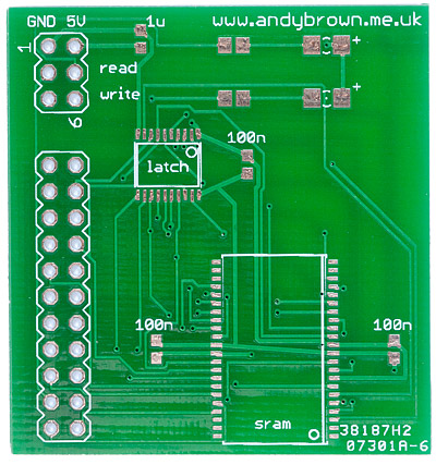
The bare PCB
Soldering SMD parts
If you google around the internet you’ll find a few articles dedicated to explaining how you can hand-solder SMD parts. The method that I use is to pre-tin all the solder pads with a normal iron and then fix the parts by reflowing the solder with a hot air gun. I use regular solder (not paste) and smelly, messy but very effective rosin flux when working with the regular iron and no-clean liquid flux when working with the hot air gun.
The secret to success here is to use an absolutely tiny amount of solder on each pad when tinning so the pad goes from flat to a tiny bump. If you create too much of a solder bump then multi-pin parts will not sit down evenly and you’ll have to manually fix them up afterwards with a fine-tip iron and a microscope.
Although the hot air station makes working with SMD parts quite simple I think in future I’ll set a minimum size of 0805 for the discrete parts because 0603 is just too fiddly to work with.
After soldering I inspect each joint with a 20x binocular (stereo) microscope and resolve any dry joints with the finest tip soldering iron that I have.
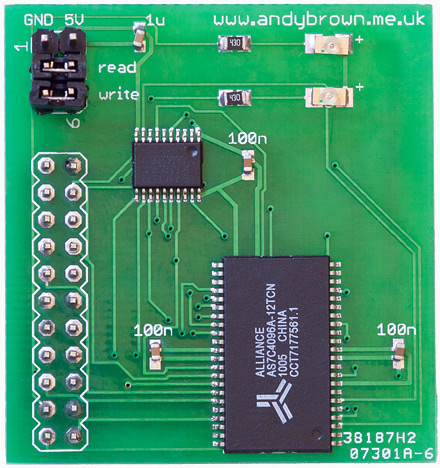
The finished PCB
The finished PCB is designed to press directly into the Arduino Mega connectors without blocking off any more pins than it uses. Finally here’s a picture of the daughterboard attached to the Arduino Mega 1280. The GND and 5V supply pins are not connected in this image.
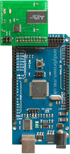
Attached to the Arduino