The Intelligent Fan Controller is designed to control the noise generated by the fans inside your computer. It does this by varying their speed based on temperatures measured inside the case. When it is cool the fans will run slowly and they will only speed up when needed... when your computer is running hot.
Anyone with a noisy computer, especially a Media Centre system in the lounge room, will benefit from this project. After installing this device, my computer is now so quiet that I can hardly tell that it is running - and that is a blessed relief.
The main features are:
- Configurable speed control based on temperatures measured inside your computer
- Control up to eight fans and measure up to four temperatures
- USB interface and Windows software for setup and monitoring
- It will run independently without the Windows software (once it has been configured)
- Cheap - The cost for all the parts is about $48
The Intelligent Fan Controller was featured in the July 2010 issue Silicon Chip magazine. Altronics are selling a full kit of parts for the Intelligent Fan Controller (Part nbr K6120). This is an easy way to get everything that you need to build the controller including a pre programmed microcontroller and a printed copy of the full magazine article - ideal if you are not an electronics expert and just want to silence your computer.
The Circuit
The circuit below shows just how simple the fan controller is. In the centre is a Microchip PIC18F2550 microcontroller, it reads the voltage from the temperature sensors LM335 (on the left) and controls the voltage converters on the right. It is by varying the voltage output of the converters that the microcontroller can control the speed of the fans.
Each voltage converter is implemented as a buck converter. The microcontroller generates a string of pulses on each output for each buck converter and, by varying the pulse width, the microcontroller can vary the output voltage. In this implementation the pulse rate is 2.5KHz and the pulse width varies between zero and 170µS to give an output between zero and 12V. Note that IC2 UDN2981A does double duty as a fast switch and a diode - both required in the buck converter design. For $2.20 this is a handy little chip.
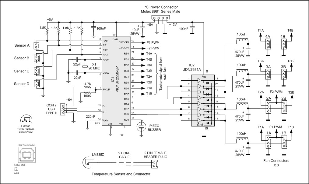
As you can see, there are four buck converters and on each output we can have a pair of fans for a total of eight fans. Each buck converter is controlled independently with different control characteristics and can drive a load of up to 250mA. As a normal computer case fan draws less than 120mA this allows you to connect two fans (as a pair) onto each output. You should check each of your fans and if they draw more that 125mA (and less than 250mA) then that fan must be the only one connected to that particular buck converter output.
This is a simple buck converter design and the output contains a lot of switching noise and is not very linear with respect to the control signal. This does not matter as a fan is just an electric motor and does not need precise control to vary its cooling power (and noise). What is important is that we control the fan's speed by varying its supply voltage. Another method of control, often used in simple designs, is to rapidly switch the fan's supply voltage off and on but that has the unwanted side effect of scrambling the tachometer output, preventing us from measuring the fan's speed.
The other components surrounding the microcontroller are standard. The buzzer is used to make an audible alarm when a fan or sensor has failed. The crystal (X1) provides the 20MHz clock and the USB connector is wired directly to the USB transceiver within the micro. The 5V provided by the computer when the USB cable is plugged in is connected to pin 1 of the micro and is used to tell the firmware when to start communicating over the USB.
Installation
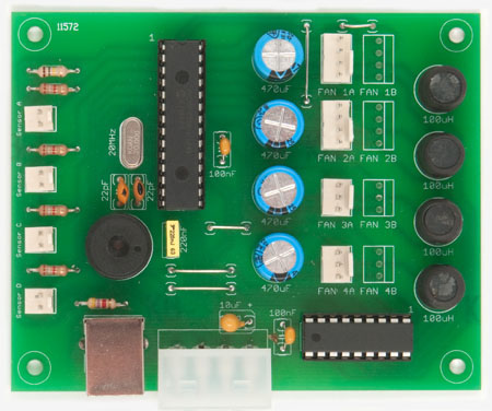
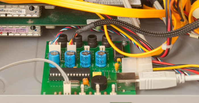
The PCB is designed to fit into a 3½ inch disk drive bay but you can place it anywhere inside your computer. Depending on the location selected you may need to make up mounting brackets to hold it in place.
The controller is designed primarily to control case fans but it can also control the fan on the CPU or graphics card. In this case you must use a dedicated sensor clamped to the heatsink and thermal conductive paste so that the fan controller can detect and respond to a rapid increase in temperature.
You can also use the controller to manage the fan inside a power supply - but these are dangerous devices with many of the components inside running at the full 230V mains potential. You should not open one up unless you know what you are doing and in that case you should not need any advice on what to do.
Downloads
Construction details (parts list, schematic, PC board, etc) - download
Part 2 - Building the Fan Controller, Construction Notes, Fan Types and temperature sensors