You can get isolation with low power consumption using this simple circuit
The circuit in this Design Idea generates a zero-crossing pulse off the ac mains and provides galvanic isolation. The falling edge of the output pulse happens at approximately 200 μsec before the zero crossing. You can use the circuit to safely stop the triggering of a thyristor gate, giving it time to properly turn off. The circuit generates short pulses only when the mains voltage is approximately 0V, thereby dissipating only 200 mW at 230V and a 50-Hz input.
 |
|
| Figure 1. | This zero-crossing detector uses low-voltage parts and consumes little power. |
The circuit charges capacitor C1 up to the limit that 22V zener diode D3 creates (Figure 1 and Reference 1). You limit the input current with resistors R1 and R5. As the input-rectified voltage drops below the C1 voltage, Q1 starts conducting and generates a pulse a few hundreds of microseconds long. The coupling of IC1 makes the response of Q1 squarer. The rms operating voltage dictates the only requirement for R1 and R5. SMD, 1206-size resistors typically withstand 200V-rms operation. This design splits the input voltage between R1 and R5, for a total rating of 400V rms. D3 limits the voltage across the bridge to 22V so that all of the subsequent components can have lower voltage ratings. A 22V zener diode can clamp as high as 30V, so this design uses a 50V, 470-nF ceramic capacitor. Ceramic capacitors have better reliability than electrolytic or tantalum capacitors, especially at higher temperatures. If you prefer a cheaper and smaller 25V part, you can change the zener diode’s voltage to 18V and still have a good margin for safety. Use R4 to limit the peak current in the LED. The primary limit on the LED current is the slope of the rectified ac input. The gradual slope doesn’t let Q1 generate current spikes when it discharges C1’s stored energy.
 |
|
| Figure 2. | In this LTspice simulation, as the input voltage drops through 0V, the LED current makes a pulse whose edges lead and lag the crossing point. The peak optocoupler-LED current is 17 mA. |
You can simulate the operation of the circuit in LTspice Version IV (Figure 2 and Reference 2). With a 230V input at 50 Hz, the simulation shows a 17-mA peak in the optocoupler LED. The simulation gives good results with inputs of 90 to 250V, both at 50 and 60 Hz. At 110V and a 60-Hz input, the LED current peak is 8.5 mA, so IC1 still works. If you need higher LED-drive currents, you can reduce the value of R3 or increase the value of C1.
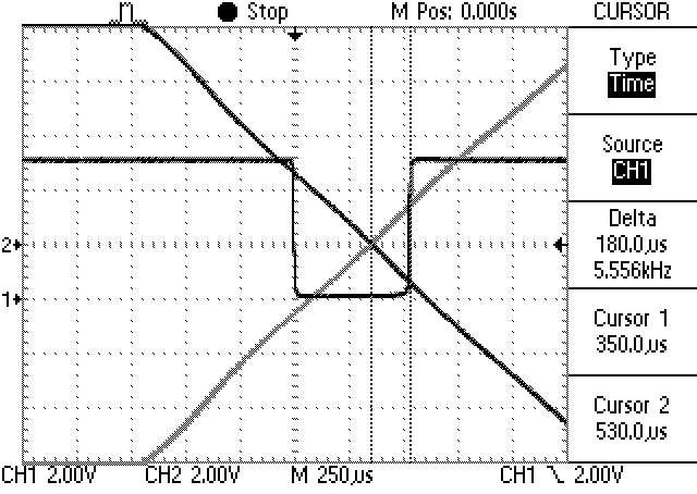
Testing a physical circuit shows good correlation with the simulation (Figure 3). Driving the isolated output from a 5V logic supply yields a good pulse waveform (Trace 1). The mains input is fed to the scope with a 15V isolation transformer for safety (Trace 2). You can use the persistence feature of the oscilloscope to show the zero-crossing point when zooming in to the transition (Figure 4). This approach allows you to accurately measure the pulse timing relative to the input zero crossing.
 |
|
| Figure 3. | Results for a prototype circuit correlate well with the simulation. |
 |
|
| Figure 4. | You can use the oscilloscope’s persistence function to relate the exact zero-crossing point to the output-pulse timing. |
References
- Demchenko, Peter, “Improved optocoupler circuits reduce current draw, resist LED aging” EDN, Dec 14, 2007, pg 60.
- “LTspice IV,” Linear Technology Corp.