By Jacques Audet Brossard, QC, Canada
Electronic Design Europe
Designers commonly use varistors in voltage limiters targeting short-duration voltage spikes typically lasting less than 10 ms. But for protection against longduration overvoltages, where the line voltage reaches more than 130 V for seconds or minutes, another solution is required. Examples include an erratic connection of the neutral wire at the distribution panel, voltage bumps on the distribution network, and overvoltage protection on ac generators.
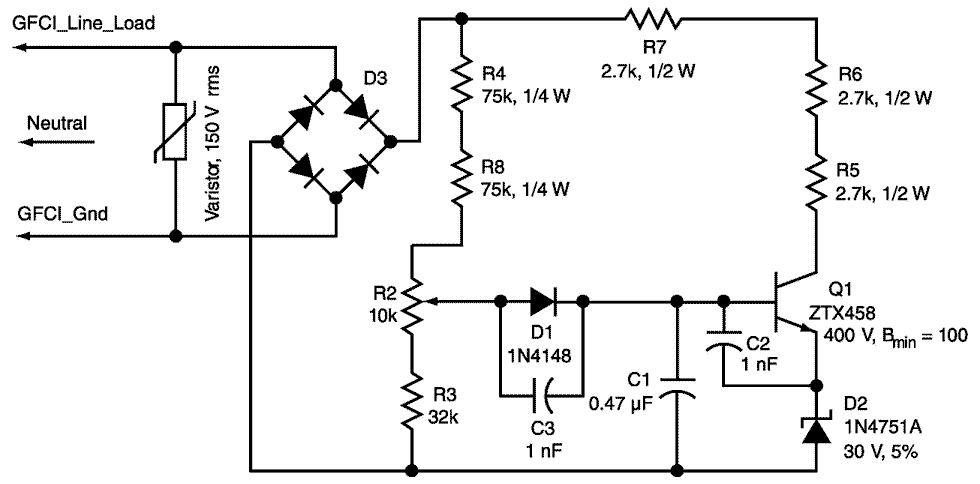
The circuit provides such overvoltage protection using a ground-fault circuit interrupter (GFCI), which has a response time of less than 25 ms when responding to ground currents over 5 mA. The circuit is connected between the GFCI load side and ground (Fig. 1). An overvoltage will cause the circuit to draw an ac current above the 5-mA trip limit of the GFCI and trigger it, disconnecting its own outlet and the remaining downstream outlets.
 |
|
| Figure 1. | Placing this two-terminal circuit between a GFCI line-load terminal and ground creates an adjustable line-voltage limiter. |
At normal line voltage, typically 120 V, transistor Q1 is barely conducting. This residual current (about 0.7 mA) comes from resistors R4, R8, R2, and R3. If the line voltage exceeds 120 V, Q1 starts to conduct a small fraction of every half cycle of the line period. Capacitor C1 and diode D1 stretch these current pulses. Resistors R4, R8, R2, and R3 make up a voltage divider with R2 allowing adjustment of the limiter voltage. The divider’s total resistance is a compromise between low residual current and a sharp knee in the circuit’s voltage-versus- current curve.
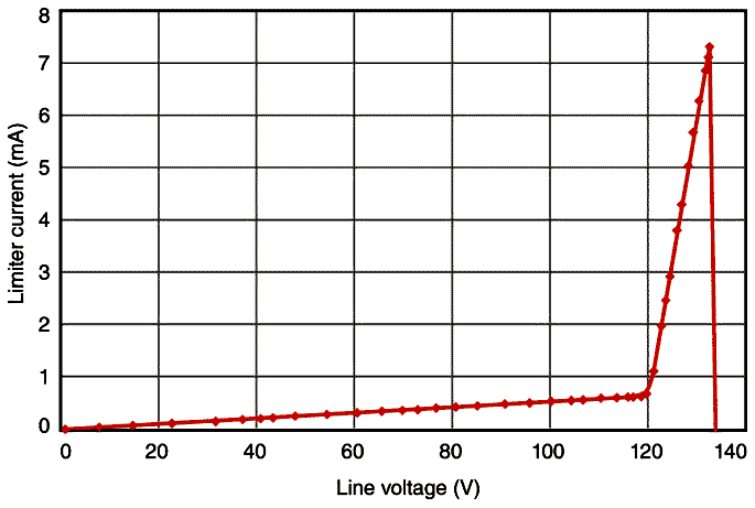
Typically, Q1 will start to conduct just above 120 V and trigger the GFCI at 133 V (Fig. 2). Q1’s collector resistors – R5, R6, and R7 – limit the current to less than 20 mA peak. They are seriesconnected to increase power dissipation and divide the peak voltages so the maximum allowable voltage across the resistors is less than 200 V under linetransient conditions.
 |
|
| Figure 2. | With the trip point set at 133 V rms, the circuit draws less than 1 mA at 120 V rms and approximately 7 mA at 133 V rms, which triggers the GFCI. |
The varistor at the circuit’s input will clamp any short-duration pulse to less than 400 V, protecting Q1. Zener diode D2 sets Q1’s threshold level of conduction. The Zener is a 1-W diode having a 40-Ω dynamic impedance to minimize reduction of the transistor’s effective current gain. Capacitors C2 and C3 shunt the D1 and Q1 base-emitter junction to prevent false activation by stray RF fields.
This circuit is easily implemented on a small printed-circuit board (PCB) at the rear of the GFCI. It can also fit in an electrical enclosure connected to an existing GFCI outlet using a standard threeprong plug. Note that this circuit will not prevent the GFCI from performing its normal protection against ground faults.