In some applications, a linear amplifier is required which has different gains with regard to the polarity of the input signal. Figure 1 shows an inverting amplifier which is linear within the second and fourth quadrants of the VOUT(VIN) plane, but the magnitude of its gain in the fourth quadrant is higher compared to the second.
|
|
|
| Figure 1. | Inverting amplifier is precisely linear within second and fourth quadrants of VOUT(VIN) plane; and has different voltage gains in these quadrants. |
The op amp IC1B acts as a differencing amplifier with a gain of:
at its inverting and non-inverting inputs respectively. These gains are constant and independent of the input signal polarity.
Polarity dependency is created in the sub-circuit built around IC1A. This sub-circuit is actually a known operational inverting half-rectifier, which outputs zero voltage for a negative input, but for a positive input, has a gain of:

The output of the inverting half-rectifier is connected to the non-inverting input of IC1B. The output signal of IC1B for positive polarity inputs, VIN+, therefore is:
From the required gain for positive input polarity,
the ratio of RN2/RN1 can be calculated, since the ratio of
equals the magnitude of gain required for negative input voltages, VIN–:
For values of resistors given in Figure 1, the magnitudes of gain are 1/3 and 1/2 respectively.
Here the magnitudes of gain are lower than 1, but can be made higher than 1 too. The only limitation is that the magnitude of gain in the 4th quadrant is higher than its counterpart in the 2nd quadrant, as illustrated in Figure 2. If, contrarily, you need higher gain in the 2nd quadrant, simply change the polarity of both diodes in the half-wave rectifier.
|
|
|
| Figure 2. | Theoretical VIN-VOUT characteristic of the amplifier. |
Ci serves as a frequency compensation of gain. Only one half of the quad op-amp is used for the circuit, leaving two amplifiers for other uses.
 |
 |
||
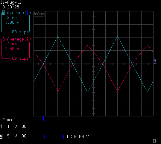
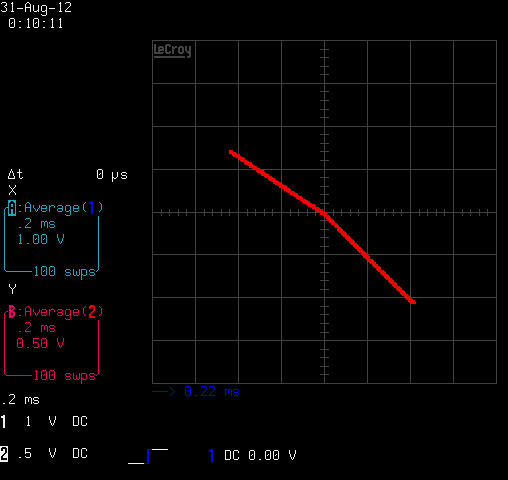
| Figure 3. | Output of circuit (purple trace) with a triangular input voltage waveform (blue trace) of 1 kHz. | Figure 4. | Input-Output (“X-Y”) characteristic of the realized amplifier. Voltage gains are –1/3 and –1/2 in the 2nd and 4th quadrants, respectively. |
This design is intended for a compensation circuit, where parasitic pulses to be compensated have different amplitudes with regard to their polarity.