Designers often use VFCs (voltage-to-frequency converters) to perform A-to-D conversion in data acquisition systems that require strict monotonic response, high resolution, reduced noise and moderate speed. The VFC produces a pulse train with frequency proportional to the input voltage. Then a microcontroller or logic converts frequency into a number by opening a gate for a fixed amount of time and counting how many pulses go through the gate for that time.
The main drawback of this approach is that to increase speed, designers have to run the VFC at high frequency, which deteriorates linearity.
This Design Idea reverses things. A circuit converts input voltage into a proportional time interval; then, the micro uses that interval to count pulses coming from its internal clock. The results are impressive:
- Good linearity as the voltage-to-period converter runs at low frequency
- Faster A-to-D conversion due to the high value of the clock frequency
- Potentially simpler program or logic, as it only has to count clock pulses, gated by the circuit
- Low price
The key is that increasing the count frequency does not affect linearity of the A-to-D conversion, while increasing the frequency of the VFC always means worse linearity.
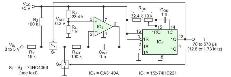
Figure 1 shows the circuit. It is a modified VFC (Ref 1), where the input voltage VIN and the reference voltage VREF swap their roles. The R1-R2 network shifts the input voltage so it is always more positive than the reference voltage and maintain proper operating conditions. The circuit uses all switches of the 74HC4066 part: two in parallel build S1 to reduce the effect of imperfect switch flatness on linearity, one switch goes for S2, and the last switch is part of the start-up circuit, paralleling CINT, and controlled by the logic during initialization, or as shown in Ref 1.
 |
|
| Figure 1. | The circuit uses a modified VFC architecture where the input voltage applies to the reference voltage terminal and vice versa. |
When the circuit gets power, the start-up circuit shorts CINT for a while and the one-shot IC2 is reset by its internal circuitry. Switch S1 opens and S2 closes. The left side of RINT connects to the ground and the right side gets the potential of 0.2 V. After the start-up time is over, the switch in parallel to CINT opens and the capacitor start charging. The integrator makes a rising ramp. When the ramp reaches the ~2.5 V threshold, the one-shot triggers. Switch S1 closes and switch S2 opens. The right side of RINT gets a positive potential that depends on the input voltage, but is always greater than 0.2 V. The current through RINT reverses direction, and CINT starts discharging. When the one-shot interval is over, the cycle repeats.
As the input voltage changes from 0 to 5 V, the output period changes from 78 to 578 µs. Integration capacitor CINT and the threshold level of the one-shot’s Schmitt input do not participate in the period vs. voltage relation. Filling the period with 10 MHz clock pulses generates numbers from 780 to 5780 – one count per millivolt. Linearity is one count or ±0.02%, which is not a surprise when the maximum frequency is only 12.8 kHz. The maximum time of the A-to-D conversion is 578 µs. This is 8.65 times faster compared to the case of a 1 MHz VFC, where it would take 5,000 µs to count 5,000 pulses of 1 µs. The interface program is short and simple; very similar to what is presented in Ref 2.
Calibration involves some back and forth due to the shift of the input voltage: adjust sensitivity to 100 µs/V using the trim-pot of the one-shot. The nominal duration of the one-shot pulse is 26 µs. Cancel the 780 count offset in the controller.
Table 1 shows that the V-to-P approach is significantly better than the V-to-F one (Refs 3, 4). Surprisingly, no chip-maker offers this type of converter.
| Table 1. | Performance of a 5,000 count A-to-D conversion with 1 MHz VFCs and the proposed circuit. |
||||||||||||||||||||||||||||
|
|||||||||||||||||||||||||||||
References
- Dimitrov J., Inexpensive VFC features good linearity and dynamic range. EDN, Design Ideas, Dec 1, 2011, pp.47-48.
- Dimitrov J., Linearize optical distance sensors with a voltage-to-frequency converter. EDN, Design Ideas, Apr 19, 2012, pp.47-48.
- AD650 voltage-to-frequency and frequency-to-voltage converter.
- VFC320 voltage-to-frequency and frequency-to-voltage converter.