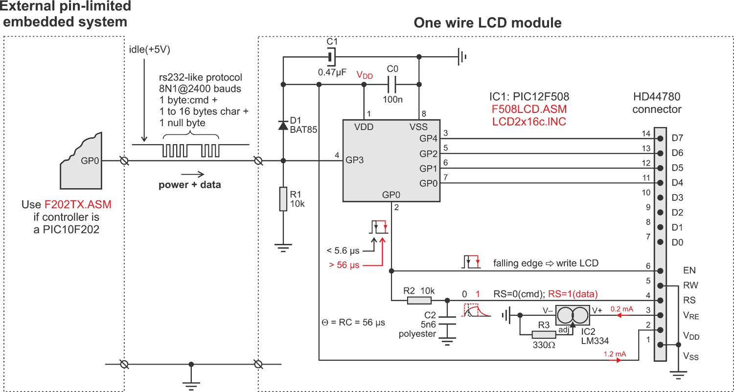
Embedded systems frequently use HD44780-type LCD displays as it is considered the most popular alphanumeric display controller. The interface comprises at least 14 pins: eight for data, three for control (EN, WR, RS), two for power supply (Vdd, Vss), and one for contrast (Vre). Configured in 8-bit mode, it requires at least 10 I/O lines (D0..D7, EN, RS). Configured in 4-bit mode, it requires at least six I/O lines (D4..D7, EN, RS). This last case seems usable when using an 8-pin PICmicro. However, 8-pin PICmicros have one pin as an input-only pin.
Many solutions for expanding I/O pins have been described in EDN Design Ideas (references 1 to 3). In a pin-limited external embedded system, if an additionnal LCD display becomes necessary, instead of changing the microcontroller with more I/O lines, it is often better (in terms of cost, and to make development easier and faster) to use this LCD module with a dedicated 8-pin PICmicro and consider it as an intelligent display.
 |
|
| Figure 1. | A low-cost one wire driven LCD module for external pin-limited system. |
The following design will be useful for any external pin-limited embedded system which needs to be interfaced to an HD44780 compatible display. Communication is via a one-wire serial link, using a simplified asynchronous protocol (8N1 at 2400 bps). It uses a very cheap 8-bit microcontroller, the PIC12F508, but any other member of the baseline PIC12F family is suitable; the program code takes less than 256 words.
The serial link is used as a command/data line (for GP3 pin) and power line (for Vdd pin, through D1 and C1). The filter R2-C2 splits the GP5 pin to two I/O lines. If GP5 outputs a pulse greater than the time constant R2*C2 = 56 µs, then input RS receives a high level, and data is written into the HD44780 display at the falling edge of the GP5 pulse.
Notice that the contrast control (LCD pin 3), instead of using a typical 10 K potentiometer, uses an LM334, which ensures a constant current of 200 µA to ground (so the contrast does not need to be adjusted as the power supply voltage decreases – if battery powered). In addition, this circuit results in a power saving of over 25% (reference 4).
F508LCD.ASM is the fully commented assembler source code (including LCD2x16c.INC). The main routine consists of displaying a 2s “splash screen”, then enters an endless loop to wait for LCD commands, each followed by a maximum of 16 bytes of LCD data, terminated by an ASCII “0”. For test purposes with an external pin-limited PICmicro, F202TX.ASM gives simple assembler source code (PIC10F202) which consists of sending another “splash screen” as a message test.
Reference
- Squeeze extra outputs from a pin-limited microcontroller (EDN | August 4, 2005).
- Microcontroller provides low-cost analog to digital conversion, drives seven-segment displays (EDN | May 10, 2007).
- RC lowpass filter expands microcomputer’s output port (EDN | June 21, 2007).
- Contrast control for LCDs (Elektor Electronics | July-August 2006, Vol.32, N°356).
Download the program files (use Save As, removing the .txt extension)